
Pressure Sensing Catheter

a technology catheter, which is applied in the field of pressure sensing catheter, can solve the problems of inconvenient intra-arterial placement, inconvenient catheter placement, and significant differences between cvcs and piccs in placement techniques and potential complications, so as to facilitate catheter placement, minimize catheter insertion-related complications, and eliminate inherent shortcomings

Inactive Publication Date: 2011-01-06
HOCH ROBERT
View PDF40 Cites 74 Cited by
  • Summary
  • Abstract
  • Description
  • Claims
  • Application Information

AI Technical Summary

Benefits of technology

In a peripherally-inserted central catheter (PICC) embodiment, an electronic pressure-sensing catheter is provided which is designed to facilitate catheter placement and minimize catheter insertion-related complications (including unintended and undesirable placement or migration of catheter tip into right heart structures) by providing real-time pressure measurement both during and post-insertion. Employment of the electronic pressure-sensing element in the embodiment eliminates need to employ conventional fluid-column manometry technique to determine CVP, thereby freeing a lumen of the catheter for other uses, while simultaneously eliminating inherent shortcomings of fluid column manometry, including introduction of infectious agents via the CVP measurement lumen and operator-dependent error in CVP measurement. In this embodiment, the electronic pressure sensing element is non-operator-dependent and does not require a venting lumen to reference atmospheric pressure, thus providing a significant advantage over existing designs and allowing for a more compact catheter design that minimizes risk of catheter-associated thrombosis of resident vessels compared with comparable larger diameter catheters. In this embodiment, more compact design extends the lower limits of patient anatomic size for which catheter may be employed for CVP determination compared with current comparable designs.
In an embodiment, the pressure sensing catheter includes at least one flexible conduit. In an embodiment, a pressure sensing catheter is provided which is designed to minimize uncontrolled bleeding, embolisms and infections. In addition, the pressure sensing catheter may be installed within a blood vessel of a patient by healthcare professionals other than physicians providing healthcare savings. In an embodiment, the pressure sensing catheter includes at least one flexible conduit which is dimensioned to longitudinally travel within a blood vessel without occluding the blood vessel. The flexible conduit includes a proximal end and a distal end. The distal end of the flexible conduit includes one or more apertures for dispensing therapeutic agents and / or other fluids into the blood vessel. The apertures are disposed near the distal end of the pressure sensing catheter such that infusion or sample withdraw does not interfere with pressure measurements.
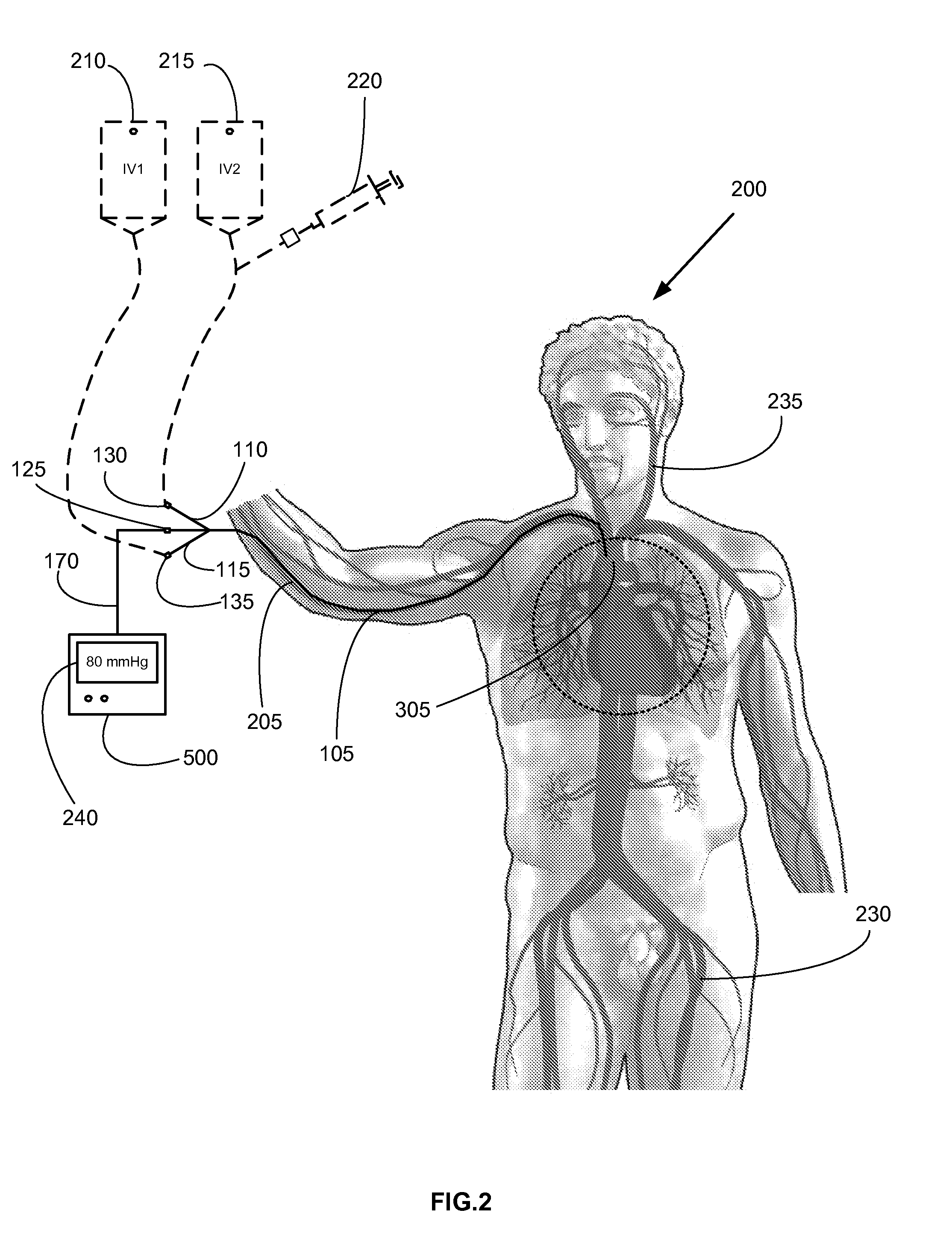
The pressure transducer is coupled at about the distal end of the flexible conduit and is used to measure vascular pressures. In an embodiment, the pressure measurements are based on changes in optical signal characteristics as part of the pressure transducer. In another embodiment, pressure measurements are based on piezoelectric properties of a nano-wire which flexes in response to pressure changes. The pressure transducer is configured to measure fluid pressure when disposed proximate to a predetermined location to be monitored, for example, within a superior vena cava of the patient. In one embodiment, the pressure transducer allows for electrical isolation of the patient from the sensing electronics which minimizes the possibility of electrical shock.
In an embodiment, at least a portion of the pressure transducer is constructed from a material having at least one electromagnetic property. For example, ferromagnetic material and / or radiographic opacity is provided in the construction of the pressure transducer or catheter material in proximity to the distal end of the flexible conduit. Alternately, or in conjunction with the electromagnetic property, a portion of the pressure transducer or catheter material may be constructed from a material having an acoustically reflective property. The electromagnetic and / or acoustically reflective properties allows a practitioner to accurately determine the location of the distal end of the pressure sensing catheter within the blood vessel to ensure proper placement of the pressure transducer. In an embodiment, the placement of the pressure transducer is within a superior vena cava or inferior vena cava.
In an embodiment, routing of the pressure sensing catheter is accomplished using a guide wire which is inserted into the flexible conduit and positioned in the proper location by the practitioner. Once the end of the guide wire is positioned in the proper vascular location, the flexible conduit is slidably positioned such that the pressure transducer is positioned at or near the end of the guide wire. The guide wire is then removed, leaving the flexible conduit and pressure sensor in the proper location within a given blood vessel. In an embodiment, the guide wire is eliminated by reducing the flexibility of the flexible conduit such that at least the outer circumference allows direct routing within a blood vessel.

Problems solved by technology

However, there are significant differences that exist between CVCs and PICCs in terms of placement techniques and potential complications.
While effective, CVC placement is not without risks.
These risks include inadvertent arterial puncture, intra-arterial placement, large vessel bleeding which may prove difficult to control, air embolism, cardiac arrhythmias and pneumothorax.
As a consequence of these significant risks, CVC placement is almost exclusively performed by a skilled physician, effectively limiting the number of those capable of performing CVC placement.
Fluid column manometry requires skilled personnel and the utilization of one the catheter's lumens (as detailed below), rendering that lumen unavailable for simultaneous use as an infusion or blood drawing port.
Due to the need for skilled operators and operator-dependent external equipment required for pressure measurements using this technique, from a practical standpoint CVP measurement is restricted to specialized settings, such as the intensive care unit (ICU) or the operating room (OR).
This fact limits the practical applicability of CVCs for measurement of CVP in the ICU / post-OR and post-hospital settings, despite potential continued need for such information to guide care.
Moreover, due to issues regarding catheter care and safety, patients are rarely discharged from hospital care to home with a percutaneous CVC still in place.
Operator-dependent variations in positioning of the external transducer height, or change in patient position after transducer positioning, can predispose to erroneous CVP measurements which can adversely affect care decisions.
Moreover, the manometer transducer measurement technique is less than ideal for PICC applications, most notably due to the very small diameter of PICCs in general, and the size of the lumen dedicated as a saline column in specific.
Kinks, blood clots or other restrictions in the saline pressure column prevent accurate measurement of CVP.
Additionally, hydrostatic forces caused by the ratio of the saline pressure column diameter vs. saline column length can additionally introduce error to the measurement of CVP.
A venting lumen occupies valuable space within the catheter and is not available for infusing or withdrawing fluids.
Catheters that use fluid column transduction of CVP do not allow for simultaneous fluid infusion or withdrawal from the CVP measurement lumen during CVP determination.
Existing multi-lumen catheter devices present limitations when bolus infusions are indicated due to semi-rigid septum wall design.
Existing designs are not intended to allow the septum wall to undulate or flex under bolus pressure.
This semi-rigidity effectively limits instantaneous volume as a bolus travels through the catheter, with a resultant increase in bolus delivery time.
The resultant increase in medication or nutrient delivery time can have a negative impact on the patient, particularly the critically ill.
In addition, conventional luminal design may be predisposed to intra-luminal thrombosis and catheter dysfunction.

Method used


Image

  • Pressure Sensing Catheter
  • Pressure Sensing Catheter
  • Pressure Sensing Catheter

Examples


Embodiment Construction

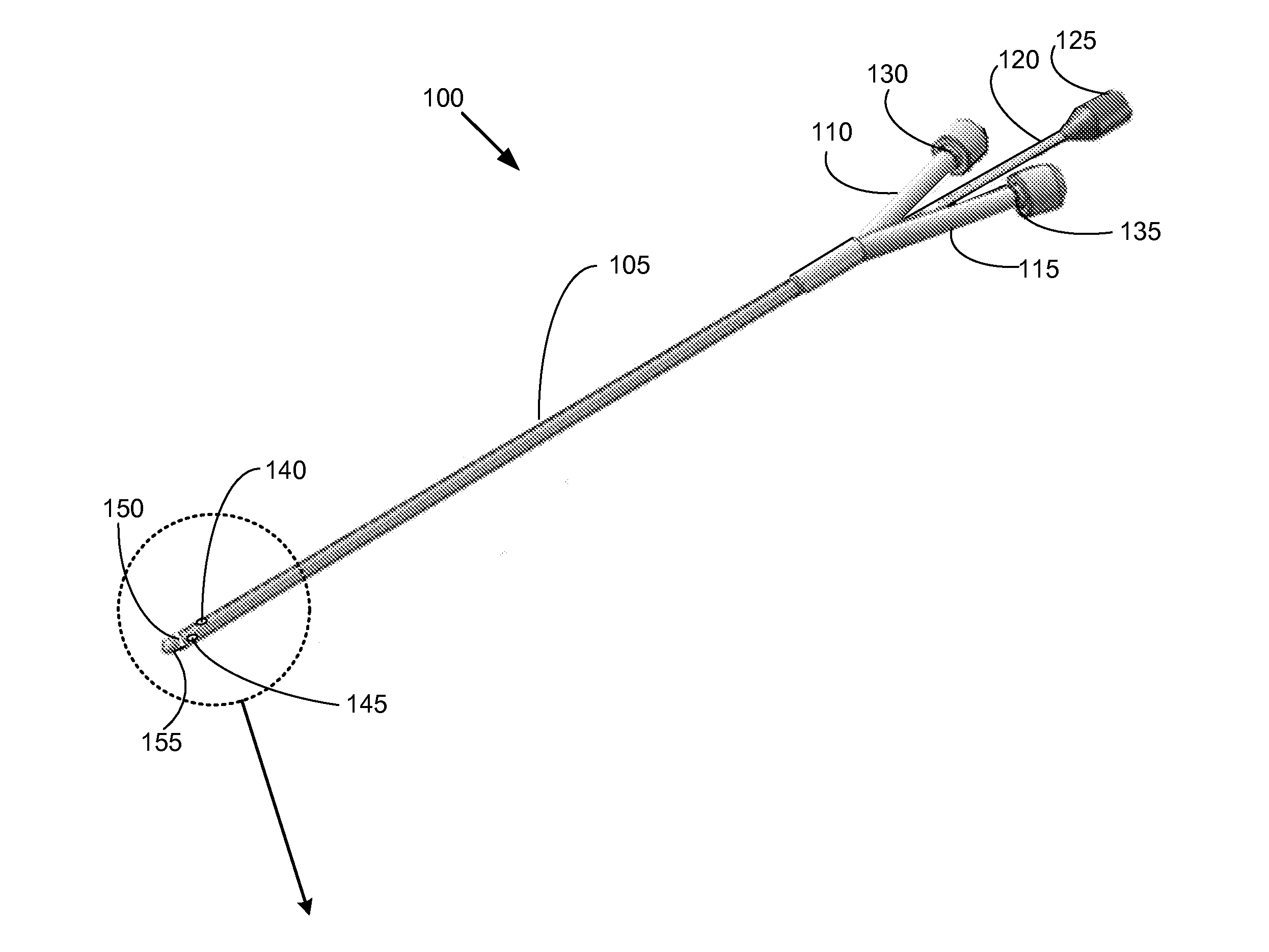
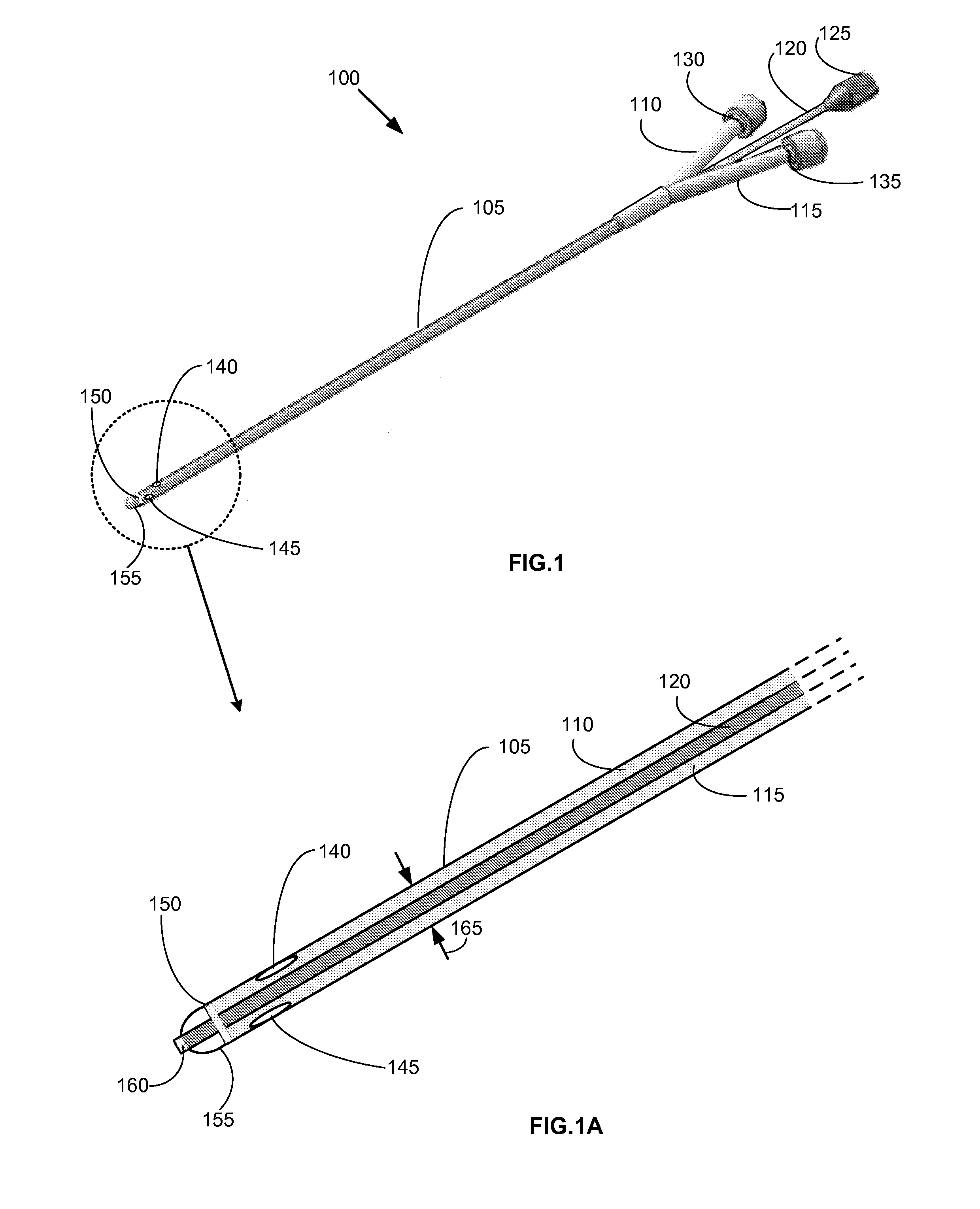
FIGS. 1, 1A provide an exemplary embodiment of a pressure sensing catheter. In an embodiment, pressure sensing catheter 100 is comprised of a flexible conduit section 105 having dual lumens 110, 115 (FIG. 1A). Each lumen 110, 115 is contiguously connected at a proximal end to a leur connector 130, 135 (FIG. 1A; shown with leur caps installed). Leur connectors 130, 135 allow for the contemporaneous infusion of fluids and / or withdrawal of fluid samples from a patient when pressure sensing catheter 100 is disposed in situ. One skilled in the art will appreciate that other types of connectors known in the relevant art may be used in lieu of the leur connectors 130, 135.

A separate signal lead connector 125 is provided at the proximal end of pressure sensing catheter 100 which facilitates coupling of a signal lead 120 with an electronic monitor 500 (FIG. 5). Signal lead 120 longitudinally extends from signal lead connector 125 to a pressure transducer 160 disposed at about a distal end of...


PUM


Abstract

A pressure sensing catheter having a proximal end and a distal end. The proximate end includes one or more leur fittings contiguous with one or more lumens disposed within the catheter, a connector coupled to a signal lead which spans the length of the pressure sensing catheter and a pressure transducer coupled at about a distal end of the pressure sensing catheter. One or more apertures are provided at about the distal end of the pressure sensing catheter to allow infusion of fluids and / or withdrawal of fluid samples contemporaneous with pressure monitoring within a blood vessel. Signals sent from the pressure transducer are converted into vascular pressure units by an electronic monitor coupled to the signal lead connector.

Description

FEDERALLY SPONSORED RESEARCH AND DEVELOPMENTNot ApplicableREFERENCE TO A MICROFICHE APPENDIXNot ApplicableTECHNICAL FIELDThis application relates to pressure sensing catheters, particularly for infusing and withdrawing of fluids from a blood vessel and for measuring fluid pressures within the blood vessel.BACKGROUNDPhysicians, healthcare professionals, veterinarians and researchers may need to establish central venous vascular access for the purpose of monitoring a patient or subject's central venous pressure (CVP), while simultaneously administering medication, hydration fluids, nutrients, radiologic contrasts, or other fluids. There are numerous clinical indications for blood withdrawal which can be facilitated by a central venous catheter. Knowledge of CVP is useful in the management of several disease states and injuries, including but not limited to shock, acute renal failure, hypotension, congestive heart failure, cerebral trauma, and spinal cord trauma. Infused fluids and man...

Claims


Application Information

Patent Timeline
Patent Type & Authority Applications(United States)
IPC IPC(8): A61M25/00
CPCA61B5/02152A61B5/412A61M25/0026A61M2025/0002A61M2025/0037H02J9/00A61M2205/3331A61M2205/3344H02J3/005H02J7/00A61M2039/082
Inventor HOCH, ROBERT C.
Owner HOCH ROBERT
Learn More