
Compositions, electrodes, methods, and systems for water electrolysis and other electrochemical techniques

a technology of water electrolysis and electrodes, applied in the field of compositions, electrodes, methods, systems for water electrolysis and other electrochemical techniques, can solve the problems of limited commercial applications, limited conversion efficiency, and considerable effort expended in water electrolysis, and achieve the effects of increasing the surface area of the catalytic material

Active Publication Date: 2011-03-03
PRESIDENT & FELLOWS OF HARVARD COLLEGE
View PDF10 Cites 50 Cited by
  • Summary
  • Abstract
  • Description
  • Claims
  • Application Information

AI Technical Summary

Benefits of technology

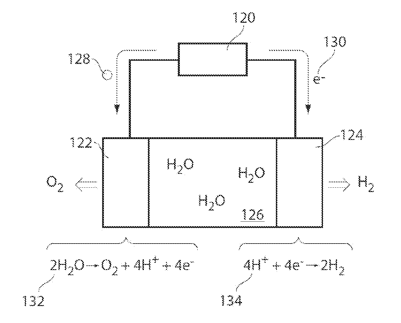
[0033]In all descriptions of the use of water for electrolysis herein, it is to be understood that the water may be provided in a liquid and / or gaseous state. The water used may be relatively pure, but need not be, and it is one advantage of the invention that relatively impure water can be used. The water provided can contain, for example, at least one impurity (e.g., halide ions such as chloride ions) and / or at least one additive (e.g., anionic species), as described herein. The presence of the at least one impurity and / or the at least one additive may have little or no substantial effect on the performance of the electrode, as described herein. In some embodiments, the pH of the water source may be at about neutral.
[0034]In some embodiments, an electrode of the present invention comprises catalytic material. In some cases, the catalytic material is associated with a current collector. Various catalytic material are described herein, including catalytic material comprising a plurality of metal elements and molecular catalysts.
[0035]In some embodiments, a catalytic material comprising a plurality of metal elements (e.g., two, three, four, five, or more, metal elements). For example, the catalytic material may be an alloy. The term “alloy,” as used herein, is given its ordinary meaning in the art and refers to a composition comprising two or more metals or metalloids that have physical properties different than those of any of the metals by themselves. Alloys may be binary, ternary, quaternary, etc., depending on the number of metals or metalloids present in the mixture. An alloy may form mixed crystals, solid solutions, or chemical compounds. An alloy may be single phase solid solutions, stoichiometric compounds or consist of two or more phases where each phase may be a solid solution or stoichiometric compound. The alloy may or might not have the same composition throughout. For example, defects may be present in the material and / or areas of higher or lower concentration of one or more of the alloy components may be present in the overall catalytic material. As another example of an alloy as that term is used herein, small regions (on the micro- or nano-scale, e.g.) of one metal may be provided, coated with another metal and / or with another metal partially or fully filling interstices of the first metal. Another example of an alloy includes a mixture of metals where the mixture is not homogeneous on the molecular scale, but includes intermixed phases of the different metals with individual regions of single metal being of micro- or nanodimensions. But an alloy is distinguished from, e.g., a series of thin layers of metal defining a multi-layered structure. The alloy may be neutral or charged. Wherever “metal,” or “metal type,” or “metal element” is used herein, it is to be understood that a metalloid can be used to fulfill the purpose of the metal, where the metalloid is suitable for the purpose of the invention.
[0036]In some embodiments, a catalytic material may comprise a composition that meets the goals of the various aspects and embodiments of the invention as described herein. With guidance from this disclosure, those of ordinary skill in the art will be able to select suitable compositions, and efficiently test them for their potential use in accordance with the invention, without undue experimentation. In some embodiments, the composition (e.g., alloy) comprises nickel. Non-limiting embodiments of compositions include binary alloys (e.g., NiMo, NiFe, NiSn, NiS, NiZn, NiP, NiW, NiCu, NiCo, NiAl, CoP, CoMo, NiTi, etc.), ternary alloys (e.g., NiMoX where X is a metal such as Fe, Cu, Zn, Co, W, Cr, Cd, V, Ti, or the like, NiCoP, NiFeP, NiFeZn, NiCoZn, NiCuFe, NiCuMo, LaNiSi, etc.), or quaternary alloys (e.g., NiCoMnAl, etc.). Each of the metals or metalloids in the composition may be present in an atomic percent between 0.001 and 99.999%, such that the total atomic percent of the metal, metalloids, and / or other elements or compounds present totals about 100%. The amount of each of the metal or metalloid component of the composition may be varied in the composition. This may be accomplished using techniques known to those of ordinary skill in the art, for example, by providing varying amounts of each of the starting material prior to forming the composition. In a particular embodiment, the catalytic material comprises or consists essentially of nickel and molybdenum.
[0037]In a particular embodiments, a composition is provided comprising molybdenum, nickel, and zinc. In some cases, a composition comprising molybdenum, nickel, and zinc may be capable of forming hydrogen gas and / or oxidizing hydrogen gas (e.g., using the methods and systems described herein).
[0038]In some cases, the composition comprises between molybdenum in an amount between about 0.1 wt % and about 90 wt % (e.g., with respect to the total weight of the composition), zinc in an amount between about 0.1 wt % and about 90 wt %, and about 0.1% and about 90% nickel. In some cases, the composition comprises molybdenum in an amount between about 1 wt % and about 50 wt %, zinc in an amount between about 0.1 wt % and about 25 wt %, and the remainder nickel (e.g., between about 25 wt % and about 98.9 wt %. In some cases, the composition comprises molybdenum in an amount between about 1 wt % and about 50 wt %, zinc in an amount between about 0.1 wt % and about 10 wt %, and the remainder nickel (e.g., between about 40 wt % and about 98.9 wt %). In some cases, the composition comprises molybdenum in an amount between about 1 wt % and about 50 wt %, zinc in an amount between about 0.1 wt % and about 5 wt %, and the remainder nickel (e.g., between about 45 wt % and about 98.9 wt %). In some cases, the composition comprises molybdenum in an amount between about 1 wt % and about 50 wt %, zinc in an amount between about 0.1 wt % and about 1 wt %, and the remainder nickel (e.g., between about 49 wt % and about 98.9 wt %). In some cases, zinc may be present in an amount of about or less than about 90 wt %, about 80 wt %, about 70 wt %, about 60 wt %, about 50 wt %, about 40 wt %, about 30 wt %, about 25 wt %, about 20 wt %, about 10 wt %, or about 5 wt %. In some cases, nickel or molybdenum may be present in an amount of about or less than about 90 wt %, about 80 wt %, about 70 wt %, about 60 wt %, about 50 wt %, about 40 wt %, about 30 wt %, about 25 wt %, about 20 wt %, about 10 wt %, or about 5 wt %. In a particular embodiment, zinc is present in an amount less than about 25 wt %. In some cases, the composition additionally comprises at least one fourth metal type in an amount up to about 50 wt %, about 40 wt %, about 30 wt %, about 20 wt %, about 10 wt %, about 5 wt %, or less. In some cases, the composition may be associated with an electrode (e.g., via electrodeposition, using a binder, etc.).

Problems solved by technology

Voltage in addition to Eo that is required to attain a given activity, referred to as overpotential, limits the conversion efficiency and considerable effort has been expended by many researchers in efforts to reduce overpotential in these reactions.
However, despite the conceptually simple generation of hydrogen by water electrolysis, the energy efficiency and capital cost associated with water electrolysis have limited commercial applications, thus many attempts have focused on the improvement of the electrolytic generation of hydrogen.
In particular, many electrodes that are used for hydrogen production may be unstable and / or inefficient for forming hydrogen gas from water comprising additives and / or impurities.

Method used


Image

  • Compositions, electrodes, methods, and systems for water electrolysis and other electrochemical techniques
  • Compositions, electrodes, methods, and systems for water electrolysis and other electrochemical techniques
  • Compositions, electrodes, methods, and systems for water electrolysis and other electrochemical techniques

Examples


example 1

[0157]The following example described the synthesis of an electrode comprising a nickel metal alloy (e.g., catalytic material) and the use of the electrode for the production of hydrogen gas from water. Specifically, platinum (Pt) and nickel molybdenum (NiMo) were evaluated for their catalytic ability to evolve hydrogen (H2) in buffered solutions containing potassium phosphate (KPi) and potassium borate (KBi).

[0158]Materials and General Methods. Potassium phosphate (monobasic), dipotassium phosphate (dibasic), sodium citrate dihydrate, ammonium hydroxide, potassium hydroxide (KOH) (VWR), boric acid (Sigma-Aldrich), nickel sulfate hexahydrate (Alfa Aesar), and sodium molybdate dihydrate (EMD Chemicals) were used as received. Buffer solutions were prepared to 1.0 M concentration, the pH adjusted with KOH, and the solutions filtered through a 0.2 μm Nylaflo membrane (VWR) prior to use. All electrochemical experiments were performed in a three electrode cell configuration using a potent...

example 2

[0163]The following example describes the preparation of stable alloys with high activity for the hydrogen evolution reaction in pH 7 phosphate and pH 9.2 borate electrolytes.

[0164]Deposition of NiMo alloy. The NiMo plating bath consists of nickel (II) sulfate hexahydrate (64 g L−1; Alfa Aesar), sodium molybdate dihydrate (48 g L−1; EMD), and sodium citrate dihydrate (60 g L−1; VWR). The pH of the bath was adjusted to 10.5 using ammonium hydroxide (VWR). NiMo was deposited onto a Pt RDE substrate at a current density of 100 mA cm−2 for one hour at a rotation rate of 2000 RPM. The resulting deposit appeared with a noticeable spiral pattern because of the rotation involved in deposition. The coloring in the spiral alternated between dark black and shiny metal with the edges consisting primarily of the shiny metal. NiMo deposits using a similar plating bath reported the presence of 75 atom % Ni and 20 atom % Mo.

[0165]Deposition of the NiFeZn alloy. The NiFeZn plating bath consists of n...

example 3

[0168]The following example describes the preparation of a stable, porous electrode with high activity for the hydrogen evolution reaction in pH 7 phosphate and pH 9.2 borate electrolytes.

[0169]Materials and Methods. Ni foam (Inco Advanced Technology Materials (Dalian)Co. Ltd; 320 g / m2, 1.7 mm thick), PtIr (20% Ir) wire (Strem Chemicals, Inc.), sodium molybdate (Na2MoO4.2H2O), nickel chloride (NiCl2.6H2O), cadmium nitrate (Cd(NO3)2.4H2O), sodium pyrophosphate (Na4P2O7.4H2O), sodium bicarbonate (NaHCO3), and hydrazine hydrate (N2H4H2O) (Aldrich) were used as received.

[0170]Deposition of NiMoCd alloy on Ni foam. The NiMoCd alloy was deposited on 1 cm2 of Ni foam (0.5 cm2 per side) as previously described. Briefly, the Ni foam substrate was immersed in a plating solution in a 3-electrode electrochemical cell containing Na2MoO4.2H2O (0.02 M), NiCl2.6H2O (0.04 M), Cd(NO3)2.4H2O (0.3 mM), Na4P2O7.4H2O (0.13 M), NaHCO3 (0.89 M), and N2H4.H2O (25 mM) at pH 7.5-9. A galvanostat was used to a...


PUM

PropertyMeasurementUnit
Fractionaaaaaaaaaa
Fractionaaaaaaaaaa
Fractionaaaaaaaaaa

Abstract

Compositions, electrodes, systems, and / or methods for water electrolysis and other electrochemical techniques are provided. In some cases, the compositions, electrodes, systems, and / or methods are for electrolysis which can be used for energy storage, particularly in the area of energy conversion, and / or production of oxygen, hydrogen, and / or oxygen and / or hydrogen containing species. In some embodiments, the water for electrolysis comprises at least one impurity and / or at least one additive which has little or no substantially affect on the performance of the electrode.

Description

RELATED APPLICATIONS[0001]This application claims the benefit of U.S. Provisional Patent Application Ser. No. 61 / 237,507, filed Aug. 27, 2009, entitled “Improved Methods and Compositions Involving Catalytic Materials, Electrodes, and Systems for Water Electrolysis and Other Electrochemical Techniques,” by Esswein, et al., U.S. Provisional Patent Application Ser. No. 61 / 266,826, filed Dec. 4, 2009, entitled “Electrodes, Methods, and Systems for Water Electrolysis and Other Electrochemical Techniques,” by Reece, et al., U.S. Provisional Patent Application Ser. No. 61 / 285,844, filed Dec. 11, 2009, entitled “Improved Methods and Compositions Involving Catalytic Materials, Electrodes, and Systems for Water Electrolysis and Other Electrochemical Techniques,” by Esswein, et al., U.S. Provisional Patent Application Ser. No. 61 / 310,084, filed Mar. 3, 2010, entitled “Electrodes, Methods, and Systems for Water Electrolysis and Other Electrochemical Techniques,” by Reece, et al., and U.S. Provi...

Claims


Application Information

Patent Timeline
IPC IPC(8): C25B1/02B01J23/889C25B11/04
CPCC25B1/04C25B11/04H01M4/86H01M4/90B01J23/8993Y02E60/50B01J23/8873B01J23/8953Y02E60/366Y02E60/36
Inventor REECE, STEVEN Y.ESSWEIN, ARTHUR J.SUNG, KIMBERLYGREEN, ZACHARY I.NOCERA, DANIEL G.
Owner PRESIDENT & FELLOWS OF HARVARD COLLEGE
Learn More