Method for position dependent change in the magnetization in an object in a magnetic resonance experiment

a magnetic resonance experiment and magnetization technology, applied in the field of magnetization position dependent change in the magnetization, can solve the problems of large mechanical loads on the mr measurement apparatus, the implementation of gradient coils reaching technical limits, and the deviation of the typical application gradient strength, etc., to reduce the length of excitation pulses and reduce signal losses

Active Publication Date: 2011-04-07
UNIVERSITATSKLINIKUM FREIBURG +1
View PDF10 Cites 12 Cited by
  • Summary
  • Abstract
  • Description
  • Claims
  • Application Information

AI Technical Summary

Benefits of technology

[0010]A further interesting application of SDMM is targeted production of a phase distribution of the transverse magnetization during excitation. In the method described in [15], a spatial phase pattern of the transverse magnetization of the nuclear spins is produced during excitation using three-dimensional selective excitation. This method at least partially compensates for dephasing of the MR signal due to susceptibility during the imaging experiment and thus reduces signal losses. This is achieved by calculating in advance the phase pattern used for phase compensation, that is, a spatial phase distribution of the transverse magnetization.
[0011]In the method disclosed in [16], such generation of phase patterns of the transverse magnetization during excitation is used to achieve partial or complete spatial encoding of the magnetic resonance signals during excitation. By repeated excitation with different phase patterns defined according to a phase encoding scheme and subsequent data acquisition on each repeat, a total data set is obtained from multiple phase encoding steps that is then reconstructed having been resolved spatially according the spatial encoding scheme and provides, for example, two- or three-dimensional images of the object under examination. This method for spatial encoding is hereinafter referred to as excitation encoding.
[0012]In the past, SDMM was initially performed using a single RF transmission antenna with an essentially homogeneous transmission field (B1 field) in conjunction with the gradient system. Inspired by the success of parallel imaging in which signal acquisition with a configuration of multiple RF antennas (also termed an antenna array in the specialist literature) consisting of a plurality of individual antennas or elements, it has now become customary to also use such antenna arrays consisting of multiple elements operated on multiple, independent RF transmission channels of the MR measurement apparatus for transmission in SDMM. In this way, it is possible to partially replace the spatial encoding, which is implemented in SDMM by analogy with data acquisition, by varying supplementary magnetic fields, by so-called sensitivity encoding and thus to reduce the length of the excitation pulses. This enables use of the different spatial variations o

Problems solved by technology

One disadvantage of the use of global gradients is that the gradient strengths required for typical applications correspond to considerable magnetic field differences between the edges of the mapping region.
Their implementation reaches technical limits to the design of gradient coils and to the design of the gradient amplifiers in terms of size and switching behavior of the electric current to be generated by the gradient coils.
Moreover, during rapid switching of these magnetic fields, rapidly changing Lorentz forces occur in the components of the MR measurement apparatus that can disadvantageously result in very large mechanical loads on the MR measurement apparatus and in excessive noise emission.
A further limitation is imposed by neural stimulation of living objects under examination due to rapidly changing magnetic field strengths, so that in many cases, the image quality that would be technically possible cannot be achieved due to physiological restrictions with respect to acoustic load and nerve stimulation.
If magnetic resonance signals from the entire examination volume are spatially encoded using such a local gradient system, it is generally not possible, in the case of non spatially selective signal generation or acquisition, to mak

Method used


Image

  • Method for position dependent change in the magnetization in an object in a magnetic resonance experiment
  • Method for position dependent change in the magnetization in an object in a magnetic resonance experiment
  • Method for position dependent change in the magnetization in an object in a magnetic resonance experiment

Examples


Embodiment Construction

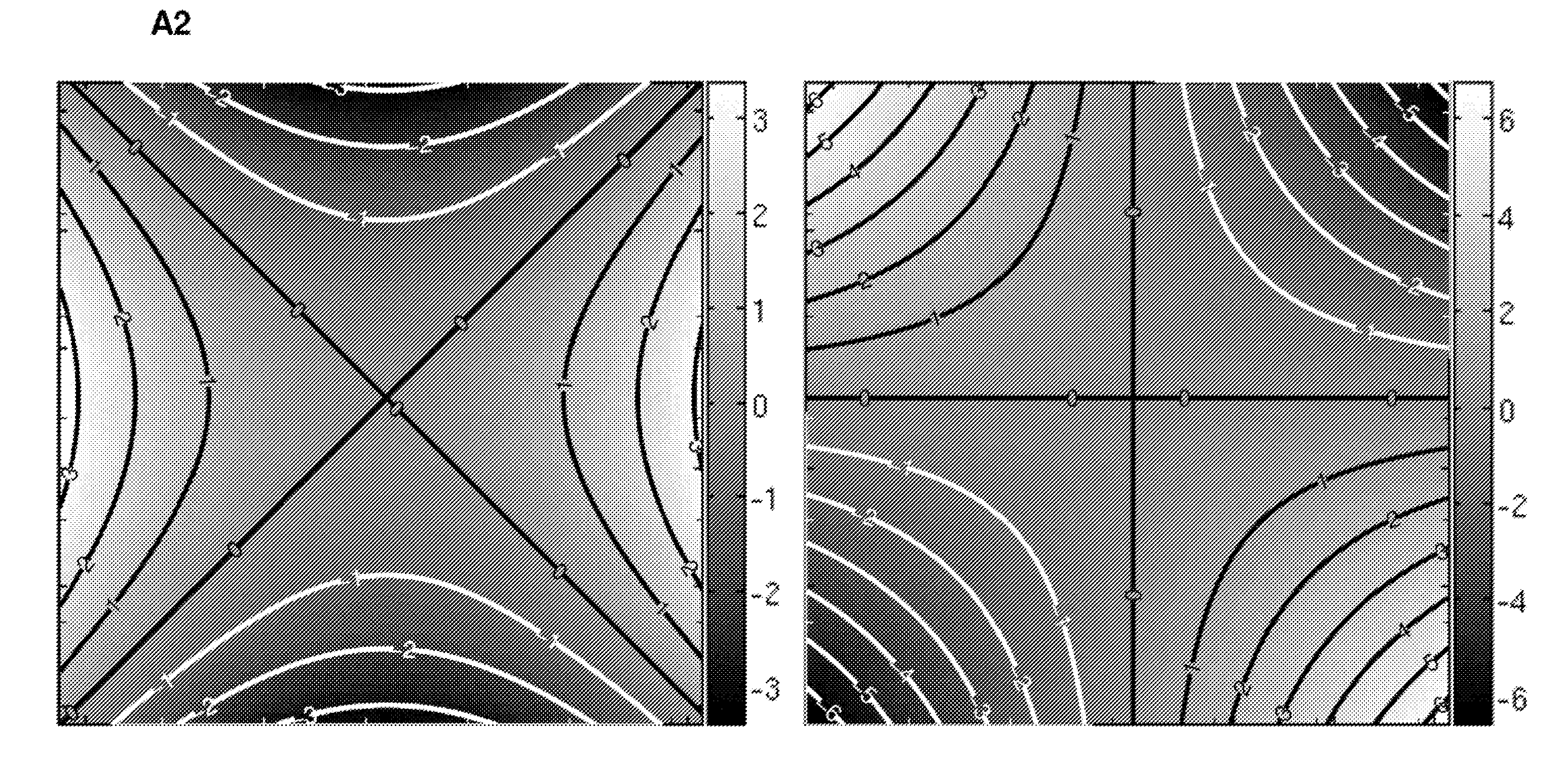
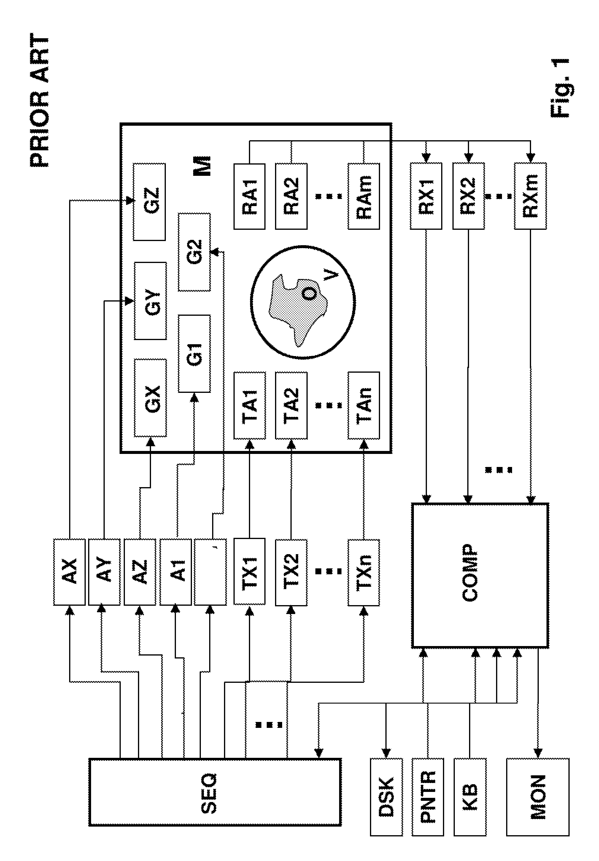
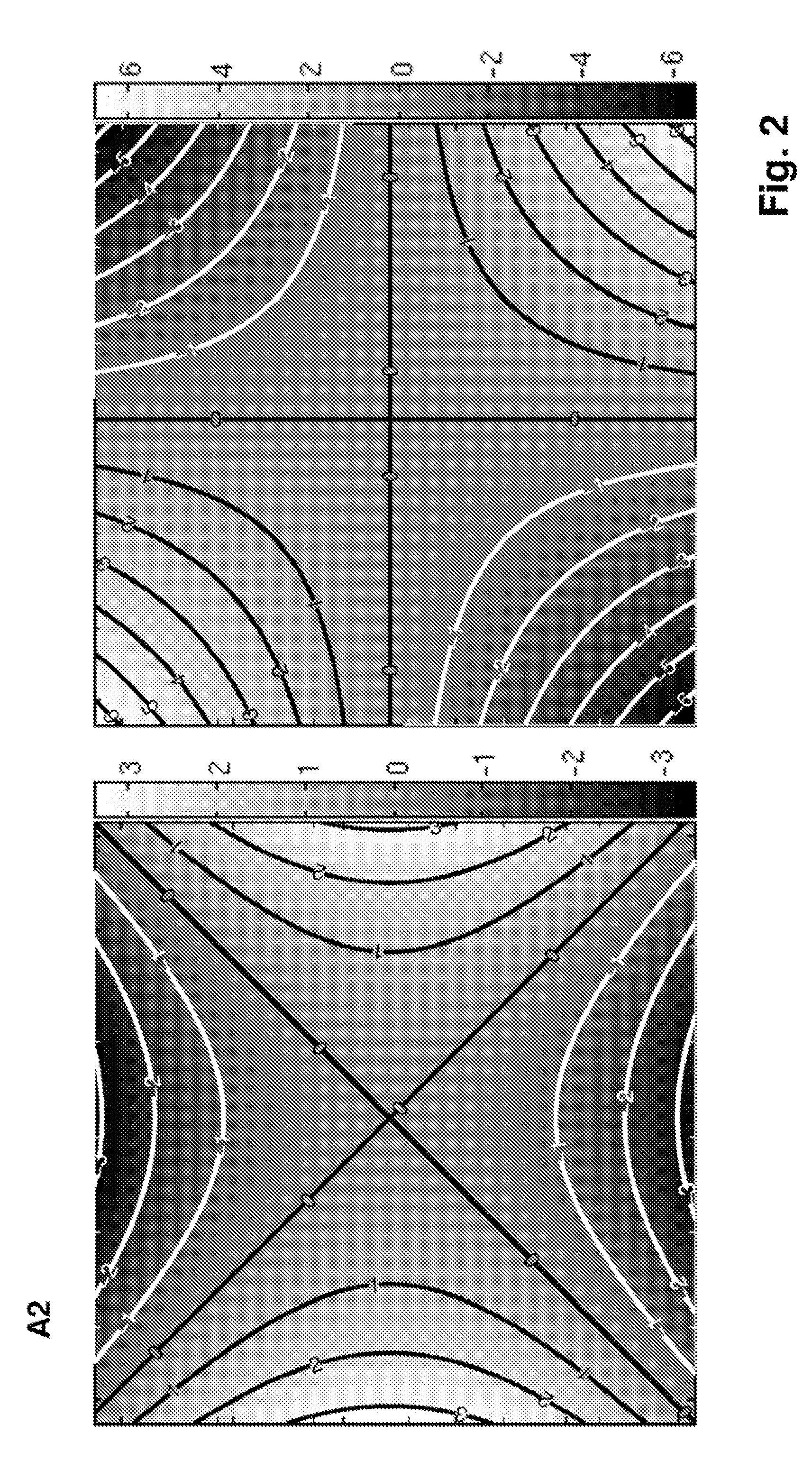
[0065]FIG. 1 schematically shows an MR measurement apparatus that is suitable for performing the inventive method. The system contains the main magnet M, with which the essentially homogeneous and static basic magnetic field is produced in a volume under examination V. The part of the object under examination that is contained in the volume under examination will subsequently be referred to as the object under examination or simply the object O. Surrounding this volume under examination V, a global gradient system, comprising three sets of gradient coils GX, GY, and GZ, and a local gradient system are put into the bore of the main magnet M with which different variants of local additional fields, local gradients, can be implemented by switching coils, usually multiple coils, to form coil combinations G1, G2. Global and local gradient systems do not have to be implemented as separate devices but may access shared gradient coils. FIG. 3 shows examples of 2 such coil combinations, G1 a...


PUM


Abstract

A method for position dependent change in the magnetization in an object, according to a requirement in a magnetic resonance measurement, wherein radio-frequency pulses are irradiated in conjunction with supplementary magnetic fields that vary in space and over time and are superposed on the static and homogeneous basic field of a magnetic resonance measurement apparatus along a z-direction, is characterized in that non-linear supplementary magnetic fields are used, whose spatial gradient of the z-component is not constant at least at one instant of the irradiation, and that the radio-frequency pulses to be irradiated are calculated in advance, wherein progressions over time of the field strengths of the supplementary magnetic fields in the region of the object that are calculated and/or measured position-dependently are included in this calculation. This enables change in the magnetization with an at least locally spatially higher resolution and/or shorter irradiation duration of the RF pulses and supplementary magnetic fields than is feasible with linear supplementary magnetic fields produced by conventional gradient systems. In particular, this is possible under the technical and physiological conditions that currently constrain the performance of the known methods using linear supplementary fields.

Description

[0001]This application claims Paris Convention priority of DE 10 2009 045 464.0 filed Oct. 7, 2009 the complete disclosure of which is hereby incorporated by reference.BACKGROUND OF THE INVENTION[0002]The invention relates to a method for position dependent change in the magnetization in an object, according to a requirement, in a magnetic resonance experiment, wherein radio-frequency pulses are irradiated in conjunction with supplementary magnetic fields varying in space and over time that are superposed on the static and homogeneous basic field of a magnetic resonance measurement apparatus along a z-direction.[0003]Such a method is known, for example, from reference [1].[0004]Magnetic resonance imaging (MRI), also termed magnet resonance tomography (MRT), is a widespread technique for non-invasive acquisition of images of the interior of an object under examination based on the spatially resolved measurement of magnetic resonance signals from the object under examination. By expos...

Claims


Application Information

Patent Timeline
IPC IPC(8): G01R33/48
CPCG01R33/3415G01R33/385G01R33/5612G01R33/4836G01R33/4833
Inventor HAAS, MARTINULLMANN, PETERRUHM, WOLFGANGZAITSEV, MAXIMHENNIG, JURGEN
Owner UNIVERSITATSKLINIKUM FREIBURG
Why Eureka
Try Eureka