

Electrostatic chuck, production method of electrostatic chuck and electrostatic chuck device
a technology of electrostatic chuck and production method, which is applied in the direction of electrical equipment, conductors, conductive materials, etc., can solve the problems of plasma corrosive gases and raise problems, and achieve the effect of large clamping for
- Summary
- Abstract
- Description
- Claims
- Application Information
AI Technical Summary
Benefits of technology
Problems solved by technology
Method used
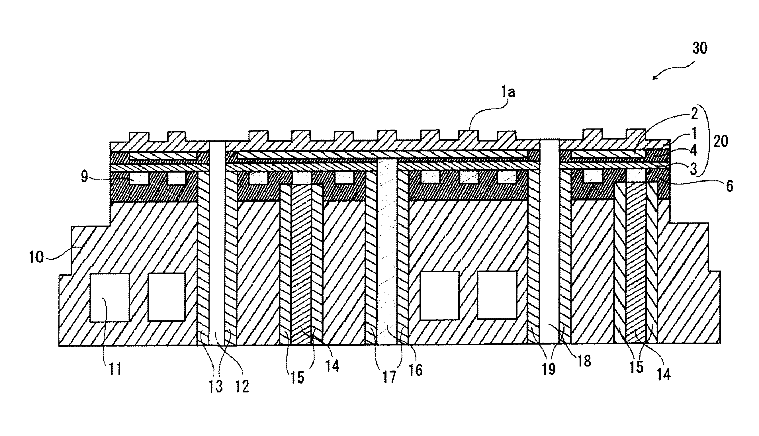
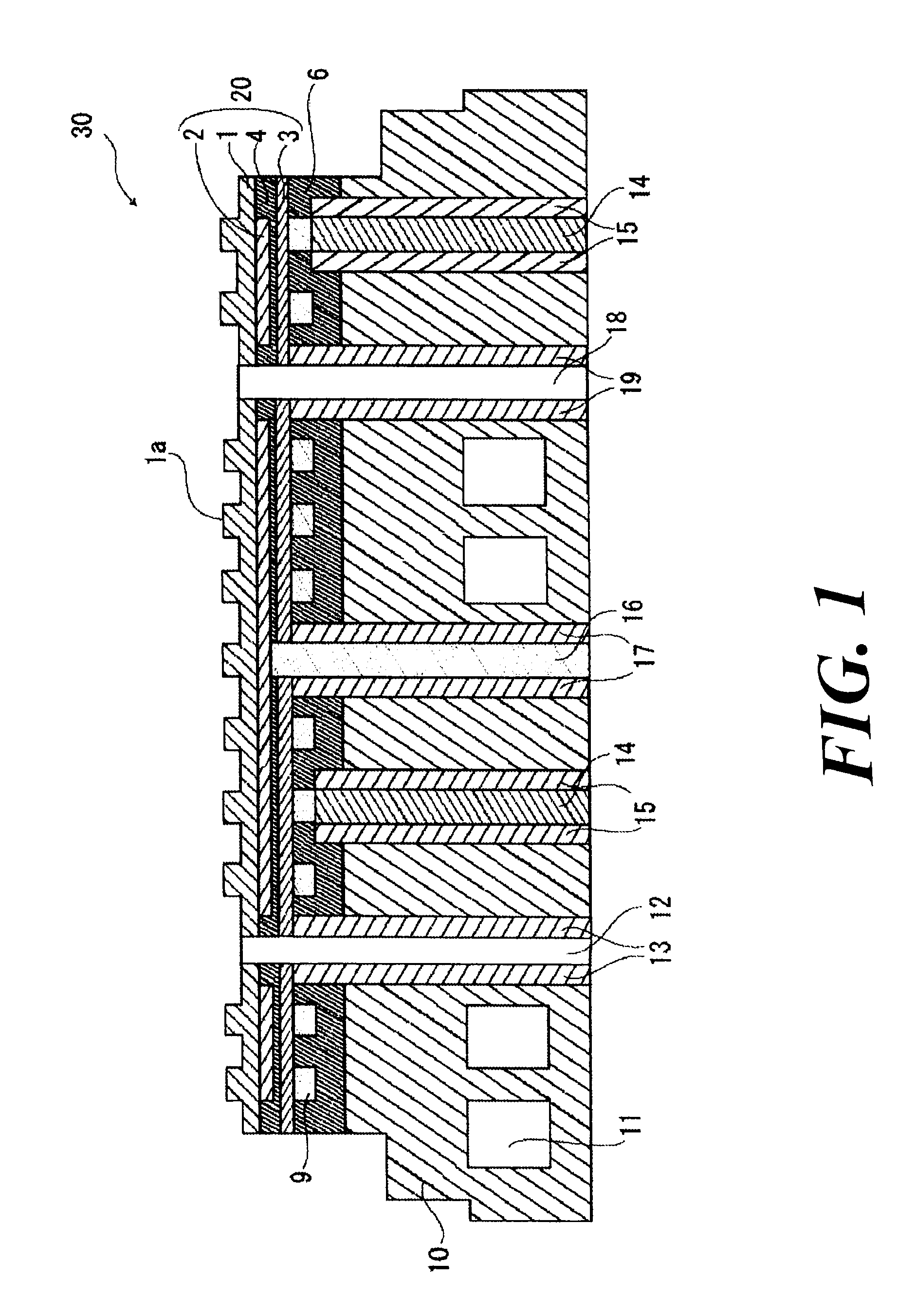
Image

Examples
examples
[0109]Next, the present invention shall be explained in more details with reference to examples, but the present invention shall by no means be restricted by these examples.
[0110]Various characteristics in the respective examples were measured according to methods shown below.
(1) Primary Average Particle Diameter of Raw Materials for Metal Oxide Powders:
[0111]Measured by means of a transmission type electron microscope (model “H-800”, manufactured by Hitachi, Ltd.).
(2) Relative Density of Sintered Body:
[0112]A density of the sintered body was measured by an Archimedes method, and a proportion (relative density) thereof to a theoretical density determined in the following manner was calculated:
[0113]
Theoretical density=unit cell weight (g) / unit cell volume (cm3)
Unit cell weight: (unit cell weight of garnet type crystal phase×mol % of crystal phase)+(unit cell weight of perovskite type crystal phase×mol % of crystal phase)+(unit cell weight of monoclinic crystal phase×mol % of crystal...
examples 1 to 6
[0125]Used were commercial aluminum oxide (Al2O3) powder, commercial yttrium oxide (Y2O3) powder, commercial samarium oxide (Sm2O3) powder and commercial gadolinium oxide (Gd2O3) powder each having a purity of about 99.9% and an average particle diameter of 0.1 μm measured by means of a transmission type electron microscope (TEM), and the above powders were weighed and controlled so that compositions shown in Table 1 were obtained. Then, they were dispersed and wet-mixed by means of a ultimizer using water as a solvent and pelletized by spray drying to prepare a mixed powder.
[0126]Next, the above mixed powder was molded into a prescribed form by a known molding means. Then, it was calcined under pressure in argon gas at 1600° C. for 2 hours by means of a hot press to prepare each sintered body. In this case, the pressure force was 20 MPa.
[0127]Various characteristics of the respective sintered bodies obtained were determined, and the results thereof are shown in Table 1.
example 7
[0128]The same operation as in Examples 1 to 6 was carried out to prepare a sintered body having a composition shown in Table 1. Then, the above sintered body was subjected to thermal treatment at 1400° C. for 12 hours in a hydrogen atmosphere. Various characteristics of the above thermally treated sintered body were determined, and the results thereof are shown in Table 1.
PUM
| Property | Measurement | Unit |
|---|---|---|
| temperature | aaaaa | aaaaa |
| temperature | aaaaa | aaaaa |
| surface temperature | aaaaa | aaaaa |
Abstract
Description
Claims
Application Information