

Fuel cell, method for operating the same, and electronic device
a fuel cell and electronic device technology, applied in the direction of fuel cells, cell components, inorganic carriers, etc., can solve the problems of difficult oxygen supply to the cathode, little research on the amount of moisture contained in the cathode, etc., and achieve the effect of high catalytic current valu
- Summary
- Abstract
- Description
- Claims
- Application Information
AI Technical Summary
Benefits of technology
Problems solved by technology
Method used
Image

Examples
first embodiment
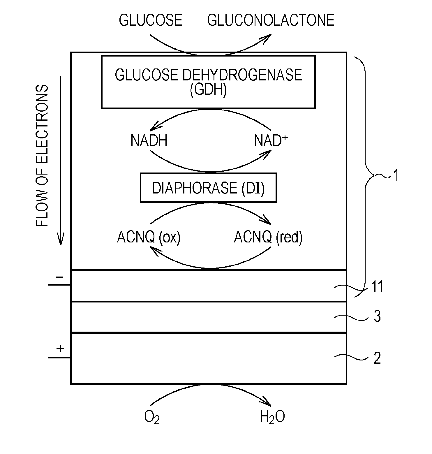
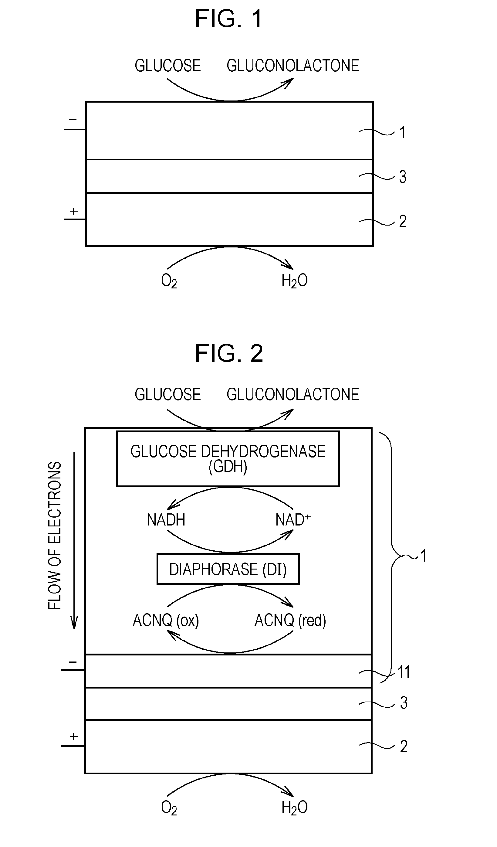
[0080]FIG. 1 schematically shows a biofuel cell according to the present invention. In this biofuel cell, glucose is used as a fuel. FIG. 2 schematically shows a detailed configuration of an anode of the biofuel cell, an example of an enzyme group immobilized on the anode, and reactions of receiving and transferring electrons caused by the enzyme group.
[0081]As shown in FIG. 1, this biofuel cell has a structure in which an anode 1 and a cathode 2 face each other with an electrolyte layer 3 that conducts only protons therebetween. The anode 1 decomposes glucose supplied as a fuel with an enzyme to extract electrons and to generate protons (H+). The cathode 2 produces water from the protons transported from the anode 1 through the electrolyte layer 3, electrons sent from the anode 1 through an external circuit, and oxygen in air, for example.
[0082]The anode 1 is constituted by immobilizing, on an electrode 11 (refer to FIG. 2) composed of, for example, porous carbon, the enzyme involv...
second embodiment
[0112]Next, a biofuel cell according to the present invention will be described.
[0113]In this biofuel cell, an electrolyte layer 3 has an electric charge having the same sign as the electric charge of an oxidized form or a reduced form of an electron mediator used in a cathode 2 and an anode 1. For example, at least a surface on the cathode 2 side of the electrolyte layer 3 is negatively charged and has a negative electric charge. Specifically, for example, a polyanion having a negative electric charge is contained in whole or a part of the portion of at least the cathode 2 side of the electrolyte layer 3. Preferably, Nafion (trade name, DuPont, USA), which is an ion-exchange resin having a fluorine-containing carbon sulfonic acid group, is used as this polyanion.
[0114]Here, a description will be made of the results of comparative experiments conducted in order to verify that when the electrolyte layer 3 has an electric charge having the same sign as the electric charge of an oxidiz...
third embodiment
[0118]Next, a biofuel cell according to the present invention will be described.
[0119]FIGS. 22(A), 22(B), and 22(C) and FIG. 23 show this biofuel cell. FIGS. 22(A), 22(B), and 22(C) are a top view, a cross-sectional view, and a rear surface view, respectively, of the biofuel cell. FIG. 23 is an exploded perspective view showing exploded individual components of the biofuel cell.
[0120]As shown in FIGS. 22(A), 22(B), and 22(C) and FIG. 23, in this biofuel cell, a cathode 2, an electrolyte layer 3, and an anode 1 are accommodated inside a space formed between a cathode current collector 51 and an anode current collector 52 so that the top and bottom thereof are sandwiched between the cathode current collector 51 and the anode current collector 52. Among the cathode current collector 51, the anode current collector 52, the cathode 2, the electrolyte layer 3, and the anode 1, adjacent components are in close contact with each other. In this case, the cathode current collector 51, the ano...
PUM
 Abstract
Description
Claims
Application Information