Exterior building wall insulation systems with hygro thermal wrap

a technology of exterior building walls and thermal wraps, applied in the field of building materials, can solve the problems of lack of moisture storage capacity, lack of fire protection and drying ability of 3-coat portland cement plaster, and prone to cracking and subsequent moisture penetration of the exterior wall, etc., to achieve the effect of accelerating water removal, improving moisture transfer, and accelerating moisture removal

Inactive Publication Date: 2011-10-20
BOMBERG MARK
View PDF2 Cites 25 Cited by
  • Summary
  • Abstract
  • Description
  • Claims
  • Application Information

AI Technical Summary

Benefits of technology

[0007]It is a principal object and advantage of the present invention to provide an external insulating system and a process of construction of that insulating system onto a wall, leading to an assembly for that accelerates drying of moisture encapsulated during construction of the building or the building enclosure.
[0008]It is an additional object and advantage of the present invention to provide a system and method for dealing with the moisture that comes from incidental rain leaks at windows or other penetrations or failures of the vapor barrier of a building or its enclosure.
[0009]It is a further object and advantage of the present invention to provide an insulated cladding system for new buildings, or retrofit to existing buildings that provides adequate rain water absorption, storage and accelerated water removal capability.
[0010]It is another object and advantage of the present invention to provide a system and method for constructing an improved transfer of moisture to an adjacent material layer having a higher activity index or higher storage capability. Other objects and advantages of the present invention will in part be apparent, and in part appear hereinafter.BRIEF SUMMARY OF THE INVENTION
[0011]The present invention recognizes that building enclosures must be designed differently for warm, mixed and cold climates and therefore the principles defined here may have different representation in each of these climatic regions. Yet, the process of construction covered by this invention comprises two interacting layers: (1) permeable or semi-permeable exterior thermal insulation and (2) a composite called here a hygrothermal or “HT” wrap. Depending on requirements of heat, air and moisture control, the thermal insulating layer may be continuous (spray or poured polyurethane foam) or constructed with boards permeable for water vapor, namely: expanded polystyrene or Eco-fiber boards. The composite “HT” wrap comprise of three layers, namely a bonding layer, a protective layer and a finishing layer. The bonding and protective layers have either identical or almost identical composition so that 3-layer system actually comprise two materials where one of them is applied in two steps.
[0012]The objective of this invention is controlling ingress of water, air and water vapor and accelerating the rate of moisture removal from the building enclosure. To this end either a thermal insulating material with measurable drainage ability (eco-fiber board such as wood fiber thermal insulation) or a special drainable thermal insulation (mineral fiber thermal insulation) may use earth gravity force for water removal. Those materials may also be used to enhance diffusion-based drying. As discussed in the section of examples, the mineral fiber insulation is inserted in the layer of spray polyurethane to enhance a combination of drainage and diffusion-based drying. In a parallel system, specially designed HT wrap with Eco-fiber board also provide enhanced capability for drying.

Problems solved by technology

Yet 3-coat Portland Cement Plaster is prone to cracking and subsequent moisture penetration.
On the other hand, “synthetic stucco” (a thin lamina reinforced with fiberglass mesh) is elastic and less prone to cracking but it does not provide sufficient fire protection and drying ability to the wall as well.
It lacks the “moisture storage capacity” of the traditional 3-coat lime-cement stucco.
Since these fibers are susceptible to moisture, the water vapor permeance of membrane changes with relative humidity.

Method used


Image

  • Exterior building wall insulation systems with hygro thermal wrap
  • Exterior building wall insulation systems with hygro thermal wrap
  • Exterior building wall insulation systems with hygro thermal wrap

Examples


example 1

Basic Concepts

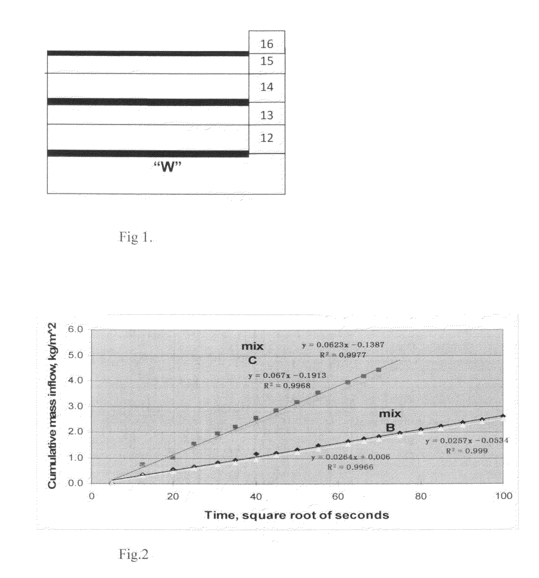
[0034]Several laboratory samples of base coat of the HT wrap 10 were prepared and tested. The sample denoted “C” in FIG. 2 was produced with the ratio hydraulic lime:fly ash:cement:sand 1:1:1:6 while sample “B” represent a traditional base-coat of Portland Cement Plaster with the ration cement:lime:sand 1:0.25:4. Mixes C and D, shown in FIGS. 2 and 3 are binder compositions that are used in the following invention. Another mix, shown in FIGS. 4 and 5, also included as a partial subject of this invention used recycled polystyrene beads.

[0035]FIG. 2 is a graph with a Lime based binder mix C shows wetting from free water surface faster than mix B that is based on the standard Portland cement. Note that faster wetting also implies faster drying of the rain wetted material.

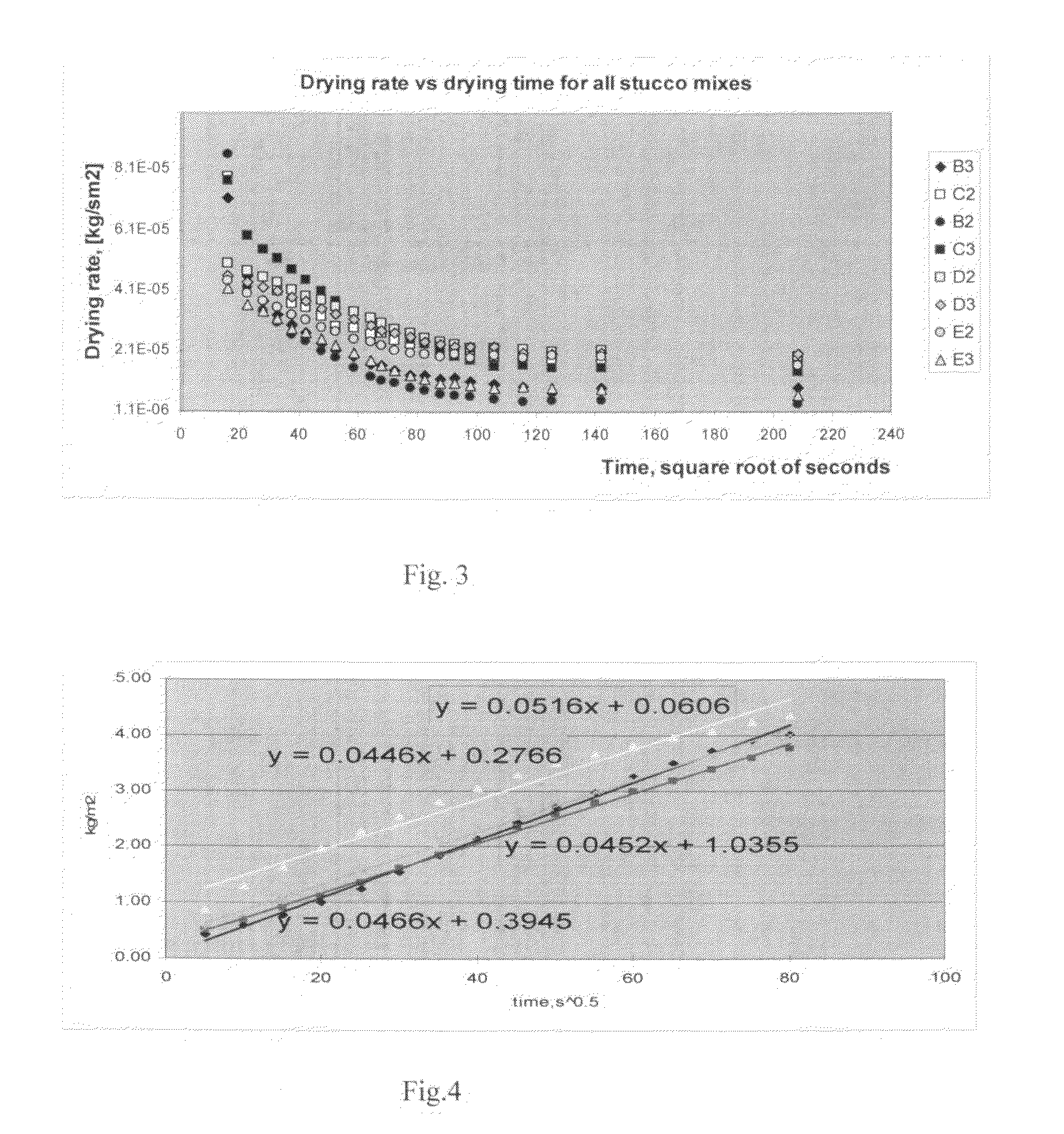
[0036]FIG. 3 is a graph showing Drying rate versus drying time measured on two specimens from different mixes (B-E). Mix B is based on standard Portland Cement, other mixes (C, D, E) are based on lime wit...

example 2

An HT wrap on Eco-Fiber Board External Insulation Systems for Cold Climate

[0040]Since 1994 flexible and rigid wood-fiber insulation boards have been produced in Germany in accordance with a standard WF-EN 13171-T3-CS (10 / Y) 20-TR7, 5-WS2, 0-MU5-AF100. When a multi-fiber system is used as an additive to the wood fibers to modify its physical properties this product is known as “Eco-fiber board”. FIG. 6 shows a system based on application of the rigid Eco-fiber board.

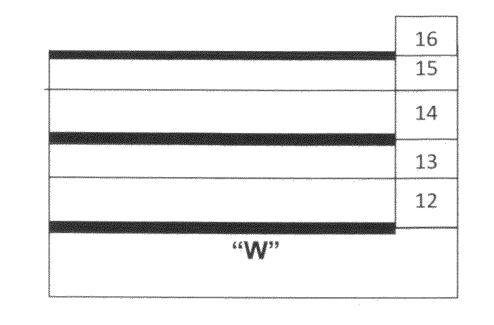
[0041]FIG. 6 is a cross-section example of an HT wrap 10, comprising layers 13-16, applied on Eco-fiber board 12 for cold climate application applied to a wall surface “W”.

[0042]The layer 12 here is Eco-fiber board from a special run of Homatherm GmbH in Berga, Germany. It has density about 120 kg / m3, a thermal conductivity measured at 10° C. equal to 0.037 W / mK or thermal resistivity of 3.9 (of hr ft2) / BTU in, specific heat 2100 J / (kgK) and thickness 80 mm (3¼ inch). It is adhered to the OSB substrate using Sto Corp manu...

example 3

Continuous External Insulation (SPF) Systems for warm climate

[0043]FIG. 7 shows an example of an HT wrap 10, comprised of layers 13-16, placed on Eco-fiber board and adhered with close cell polyurethane foam onto a wall surface “W” in warm climate application.

[0044]The insulation layer 12 represented here may be made of 1½ inch thick, close or open cell polyurethane foam. This could be either poured foam, applied with a typical 4 ft (1.2 m) height, between extruded polystyrene strips placed on each stud serving as both distance marks and locations of the mechanical fasteners locations or 2 component pressurized froth. In the latter case the maximum height of the insulation board is 2 ft (60 cm). In the actual example 3 different foams from two different manufacturers were used. One of the foams had CCMC 12840-Report that describes the technical features as follows: The final cured product has a nominal density of 30.4 kg / m3 and an assigned design thermal resistance of 1.05 m2·° C. / W...


PUM

PropertyMeasurementUnit
thicknessaaaaaaaaaa
shrinkageaaaaaaaaaa
densityaaaaaaaaaa

Abstract

A composite, layered, thermal insulation and cladding system and method to construct a hygro thermal (HT) wrap. The external insulation system controls the passage of heat, air, liquid water, water vapor, and moisture permeability of the system with the change of the moisture content in some materials. The HT wrap comprises at a material mix applied in two layers, with or without additional surface treatments. The inventive method includes the material combinations and their fiber diameter or particle size in such a manner that the microstructure of HT wrap will provide pore space for retention of the initially added water, permit expansion of the freezing water (thereby improving freeze-thaw durability), provide the interruption in the crack propagation (because the brittle inorganic matrix of the binders is prone to cracking), and provide a degree of elasticity needed to accommodate movements caused by the polyurethane foam or other substrates.

Description

BACKGROUND OF THE INVENTION[0001]1. Field of Invention[0002]The present invention relates to building materials and more specifically, to a composite exterior insulation system and cladding used in the construction of building walls and structure, to control heat transfer, rain-water penetration, air and water vapor transmission through a building enclosure, and is based upon Provisional Patent Application Ser. Nos. 61 / 342,513 filed 15 Apr. 2010, and 61 / 399,497 filed 13 Jul. 2010, each being incorporated herein by reference in their entirety.[0003]2. Description of Prior Art[0004]A building wall's typical exterior insulation layer includes a thermal insulating material covered by a rain intrusion protection layer such as siding or stucco. Thermal insulation material can be impermeable or permeable to water vapor. Stucco can be a “three-coat stucco” (for example, a 3-coat, traditional, metal-lath-reinforced, cladding system) or one-coat stucco (for example, a reinforced portion, appl...

Claims


Application Information

Patent Timeline
Patent Type & Authority Applications(United States)
IPC IPC(8): B32B5/02
CPCE04B1/625Y10T442/10
Inventor BOMBERG, MARK
Owner BOMBERG MARK
Why Eureka
Try Eureka