Sub-micron surface plasmon resonance sensor systems

a plasmon resonance sensor and micro-micron surface technology, applied in the field of sub-micron surface plasmon resonance sensor systems, can solve the problems of losing surface localization properties, affecting the sensitivity of micro-sensors, and rendering whispering gallery modes ineffective in microsphere environments, etc., to achieve the effect of enhancing the sensitivity and speed of micro-sensor detection, reducing the profile of the present mspr sensor, and eliminating complicated optics

Active Publication Date: 2011-10-20
THE TRUSTEES OF INDIANA UNIV
View PDF6 Cites 28 Cited by
  • Summary
  • Abstract
  • Description
  • Claims
  • Application Information

AI Technical Summary

Benefits of technology

[0072]One benefit of the present invention is the elimination of the complicated optics required for conventional planar sensors. For instance, the MSPR sensor of the present invention can use diffuse light from a low-cost light source. The light need not be polarized, filtered or directed. The present invention eliminates the need for fragile and bulky optical alignment components, such as the goniometric mounts in some prior systems.
[0073]A further benefit of the MSPR sensor of this invention resides in its capabil

Problems solved by technology

Despite certain advantages over other technologies like mass spectroscopy or ELISA because it allows label-free real-time monitoring of molecular interactions, classical SPR suffers from disadvantages that have prevented its use in potentially much larger fields including bio-defense, forensics diagnostics, high-throughput drug discovery, or point-of-care testing (POCT) for human and veterinary d

Method used


Image

  • Sub-micron surface plasmon resonance sensor systems
  • Sub-micron surface plasmon resonance sensor systems
  • Sub-micron surface plasmon resonance sensor systems

Examples


example 1

Fabrication of an MSPR Sensor

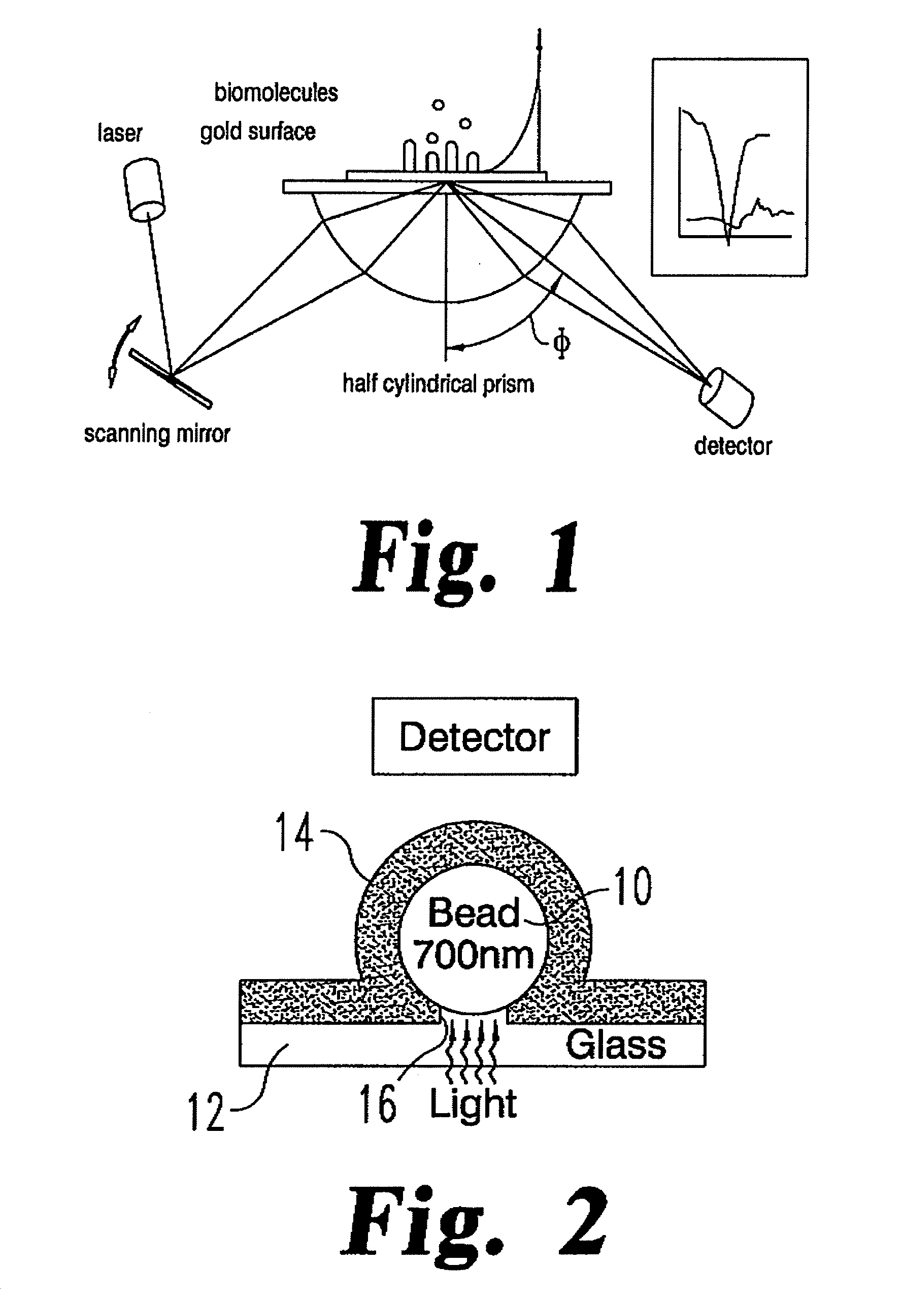
[0146]The following is a description of one method for laboratory fabrication of the MSPR sensor shown in FIG. 2. It is understood that other fabrication techniques are possible for specific applications. It is further understood that the immediately following description is principally for a sensor adapted for research use, rather than for commercial application, although the same principles may be applied to produce a commercially viable sensor.

[0147]Microscope cover glasses No. 1, 30×24 mm, 156 μm thick, are scored with a diamond and broken into four equal pieces. Also, microscope slides, 25 mm×75 mm are scored and broken into two equal pieces. The slides and cover glasses (items 12, 62 and 64, respectively, in FIGS. 2 and 4) are cleaned using a modified version of the well-known RCA cleaning protocol (H2O2:H2O:NH4OH-2:1:2, warmed to 70° C.) followed by rinsing in DI water and drying with N2. The cleaned cover glasses are placed in a dry atmosphere in...

example 2

Fabrication of a Micro-Fluidics Chip with MSPR Sensors

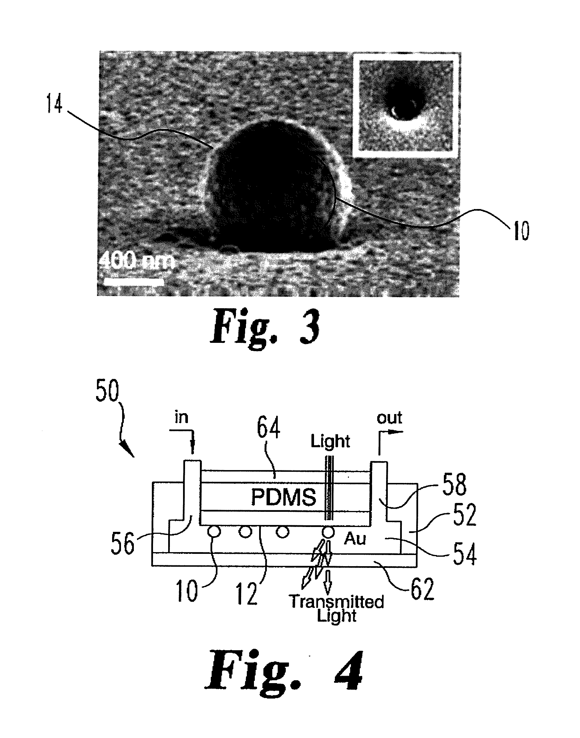
[0149]According to another embodiment of the invention, a process is provided for the fabrication of the sensors of the present invention in a micro-fluidic chip, such as the chip 50 shown in FIG. 4. Variations of the same protocol will allow fabrication of more complex sensors. In this process, the MSPR sensors are mounted within a housing, which in the preferred embodiments is in the form of a micro-chip. The micro-chip format for the MSPR sensor allows the sensor to be readily integrated into micro-systems, such as a micro-fluidics chip described herein.

[0150]In accordance with this embodiment, the fluidics chip is made using photolithographic technology and chip replica molding in polydimethylsiloxane (PDMS). The fluidics devices are fabricated using the negative-tone photoresist SU-8 as a master to cast PDMS channel structures. The master substrates are 50 mm×50 mm glass slides. The substrates are cleaned in HCl:HNO3 (3:1), ...

example 3

Operation of the Micro-Fluidics MSPR Sensor Chip

[0155]In one method of using the micro-fluidics chip 50 (FIG. 4), fluid connections from the fluidics chip to fluid reservoirs, such as a syringe or a fluid pump, are made using 1.6 mm OD polypropylene tubing. The flows are controlled by adjusting the height of the reservoir connected to the input channel 56 relative to the height of the reservoirs connected to the output channel 58, or controlled by the fluid pump, so that a stable flow of about 1 μL / s achieved. After the chip is connected to the reservoirs it is placed on a piezo-driven stage capable of motion in all three directions (3D) that can position the sensor chip in space with a precision of 10 nm. The whole ensemble is placed under an inverted microscope and microscope objectives of 40× and 60× are used to collect and analyze the signal coming from a single sensor.

[0156]The functionality and sensitivity of the MSPR sensor 50 may be evaluated using an experimental set-up sho...


PUM


Abstract

Wearable or implantable devices combining microfluidic control of sample and reagent flow and micro-cavity surface plasmon resonance sensors functionalized with surface treatments or coatings capable of specifically binding to target analytes, ligands, or molecules in a bodily fluid are provided. The devices can be used to determine the presence and concentration of target analytes in the bodily fluids and thereby help diagnose, monitor or detect changes in disease conditions.

Description

CROSS-REFERENCE TO RELATED APPLICATIONS[0001]This application is a continuation-in-part application of co-pending U.S. patent application Ser. No. 12 / 751,099, filed Mar. 31, 2010, entitled “Sub-Micron Surface Plasmon Resonance Sensor Systems” and co-pending U.S. patent application Ser. No. 12 / 751,101, filed Mar. 31, 2010, entitled “Sub-Micron Surface Plasmon Resonance Sensor Systems,” which are divisional applications of U.S. patent application Ser. No. 11 / 611,509, filed Dec. 15, 2006, entitled “Sub-Micron Surface Plasmon Resonance Sensor Systems,” which claims priority under 35 U.S.C. §119(e) to U.S. provisional application Ser. No. 60 / 750,872, filed on Dec. 16, 2005, entitled “Sub-micron Cavity Surface Plasmon Sensors and Their Micro-fluidic Applications”, the entire disclosure of each is incorporated by reference herein.GOVERNMENTAL INTEREST[0002]This invention was made with government support under IBN-0083653 and NAG2-1619 awarded by the National Science Foundation and from NAS...

Claims


Application Information

Patent Timeline
IPC IPC(8): A61B5/1455
CPCB82Y15/00B82Y30/00G01N2021/0346G01N21/554G01N21/05
Inventor GLAZIER, JAMES A.AMARIE, DRAGOS
Owner THE TRUSTEES OF INDIANA UNIV
Why Eureka
Try Eureka