
Bio-Hybrid Implant for Connecting a Neural Interface With a Host Nervous System

Inactive Publication Date: 2011-10-20
INTERUNIVERSITAIR MICRO ELECTRONICS CENT (IMEC VZW) +1
View PDF0 Cites 24 Cited by
  • Summary
  • Abstract
  • Description
  • Claims
  • Application Information

AI Technical Summary

Benefits of technology

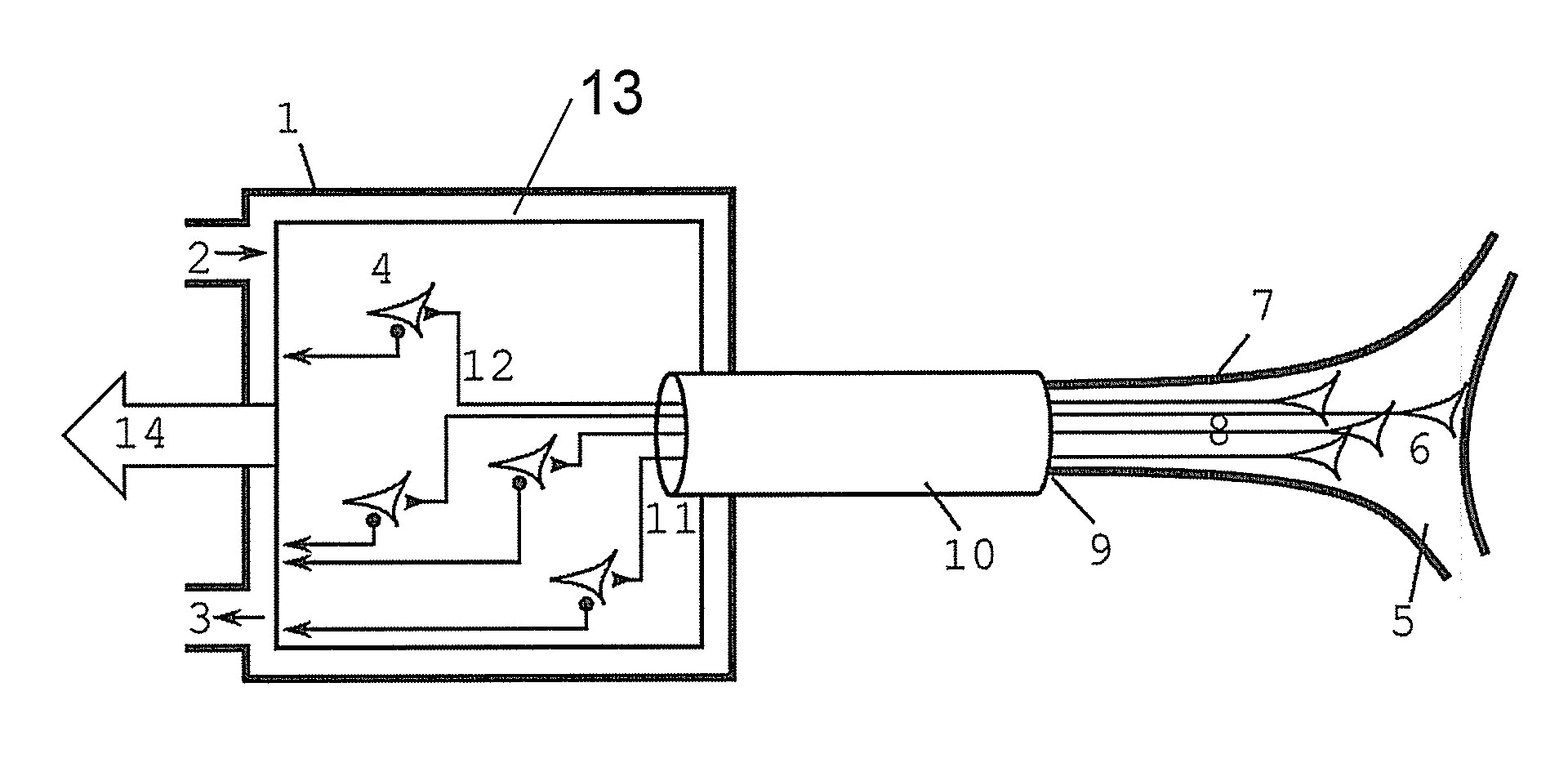
[0022]The bio-hybrid implant of the present disclosure further differs from existing interface systems in the fact that the electronic system (in this application referred to in general as the Neuronal Transducer Array (NTA)) is situated outside the living tissue of interest (e.g., outside the brain) or alternatively within a non-critical tissue area (e.g., beneath skin). By letting in-vitro cultured neurites grow into the tissue of interest or alternatively let host's neurites grow outside its tissue it is possible that the actual connection with the Neuronal Transducer Array (NTA) can be made outside the tissue of interest in an insulated and controlled environment thereby reducing the risk of contamination significantly. The closed system can thereby efficiently separate the hosts' immune system from the cultured neurons, thereby reducing the risk of inflammation at the interface and reducing the risk of corrosion of the electrodes.
[0050]The method for manufacturing the implant of the present disclosure may further comprise the step of providing at least one of an electronic circuit, a chip, a multi-electrode array (MEA), a biosensor, an optical sensor, an optical stimulator and the method may furthermore comprise the step of providing further electronic devices for interfacing with the at least one guiding channel and micro-fluidic devices for viability of the cells.

Problems solved by technology

However these probe like systems encounter problems when a further advanced neuroprosthetic interface has to be realized, e.g., connecting a semiconductor device to the neural network.
The major problems in this case are:1. The ability to record neuronal signals with good Signal to Noise and Interference Ratio (SNIR) which requires that the electrodes need to be in close contact with the target neurons.2. Damage to the target neurons and neurites due to a surgical procedure while implanting in the electrodes.3. Long-term mechanical injury due to micro-motion of the probe relative to the brain.4. Long-term alteration of the nervous tissue caused by neuro-inflammation (foreign-body reaction).5. Reduction of the lifetime of the electrodes due to corrosion.6. Lowering the power consumption of the implant, worsened by electrical stimulation of non-specific (large) targets, and low-SNR recording circuits resulting in complex data acquisition circuits and signal processing to interpret the signals.

Method used


Image

  • Bio-Hybrid Implant for Connecting a Neural Interface With a Host Nervous System
  • Bio-Hybrid Implant for Connecting a Neural Interface With a Host Nervous System
  • Bio-Hybrid Implant for Connecting a Neural Interface With a Host Nervous System

Examples


first embodiment

[0080]According to the first aspect, the present disclosure relates to a bio-hybrid implant for guiding and connecting a host's efferent neurons, also known as motor or effector neurons, towards an insulated system containing the Neuronal Transducer Array. The insulated system may preferably furthermore contain in-vitro cultured neurons.

[0081]FIG. 1 illustrates a schematic representation of such bio-hybrid implant according to the first embodiment of the first aspect of the present disclosure, connecting to an efferent (e.g., motor) nerve 7. Three main blocks can be seen in this bio-hybrid system. A first block comprises an insulated chamber 1 containing the Neuronal Transducer Array 13, for example a MEA. In the embodiment illustrated, the insulated chamber 1 furthermore comprises electronic devices for interfacing, and micro-fluidic apparatus for providing viability of the cells. A second block comprises at least one flexible guiding channel 10, optionally bundled in a further fle...

second embodiment

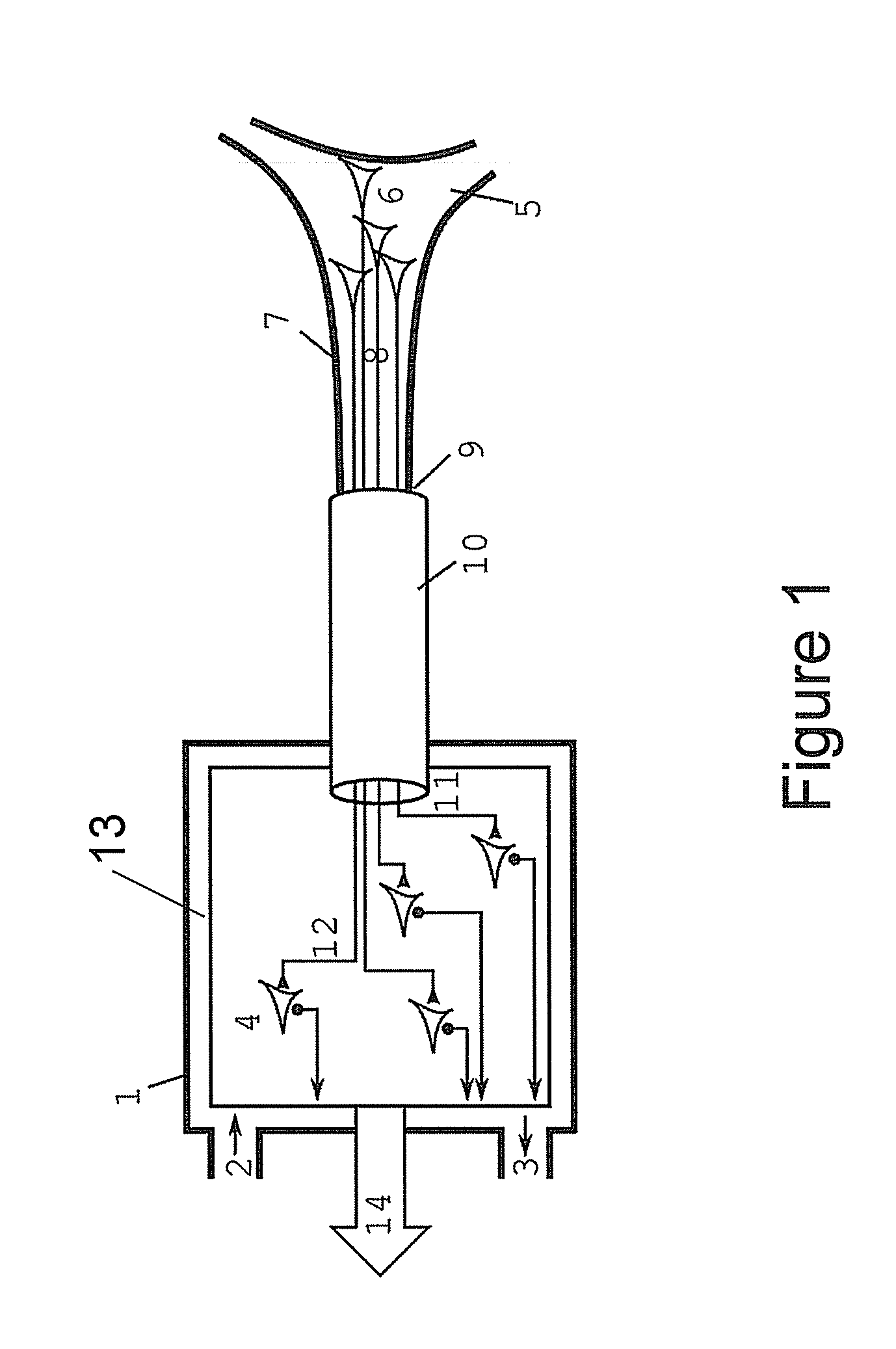
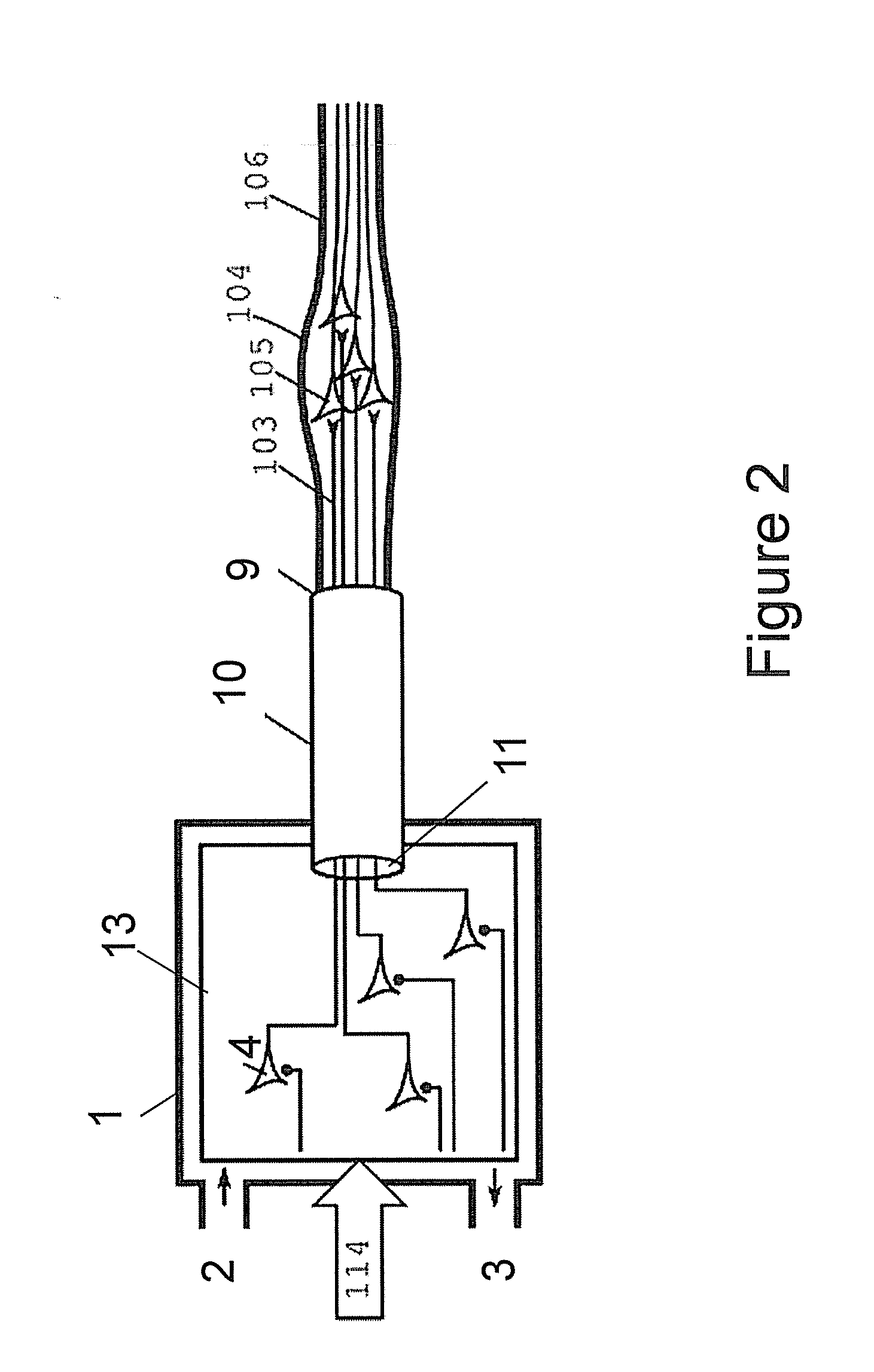
[0085]According to the first aspect, the present disclosure relates to a bio-hybrid implant for guiding in-vitro cultured neurons through the guiding channel towards the host's nervous system thereby making contact to e.g., an afferent nerve, also known as sensory or receptor nerve.

[0086]A schematic representation of a bio-hybrid implant according to this embodiment is shown in FIG. 2. The bio-hybrid implant comprises an insulated chamber 1 containing the Neuronal Transducer Array 13, for example a MEA. In the embodiment illustrated, the insulated chamber 1 furthermore comprises in vitro cultured neurons 4, micro-fluidic apparatus for providing viability of the in vitro cultured neurons 4 and electronic devices for interfacing with the in vitro cultured neurons. The insulated chamber 1 may further contain an inlet 2 and an outlet 3 of a fluidic, e.g., microfluidic, system, providing the in vitro culture medium with oxygen, growth factors, and other (bio) chemical support as needed. ...

third embodiment

[0092]According to the first aspect, the present disclosure relates to a bio-hybrid implant as shown in FIG. 3, where axons 103 originating from in-vitro cultured cells 4 are guided through at least one guiding channel 10, and make synaptic connections with the nodes of Ranvier 202 of myelated axons 203 in a peripheral nerve system (PNS) or Central Nerve system (CNS). Hereto, the at least one guiding channel 10 may be provided with openings 103 along its longitudinal surface, the openings 103 being arranged for letting the axons 103 originating from the in vitro cultured cells 4 leave the at least one guiding channel 10.


PUM


Abstract

A bio-hybrid implant suitable for recording and / or stimulating cells, the implant comprising (a) at least one closed insulated chamber (1) containing a substrate (502) with a neural interface (13) for connecting neurons to an electronic circuit, (b) at least one flexible guiding channel (10) having a first interface (11) to connect to at least one of the closed insulated chambers (1) and a second interface (9) to connect to a hosts' nerve system (7) or to another insulated chamber.

Description

BACKGROUND OF THE INVENTION[0001]1. Field of the Invention[0002]The present disclosure relates to the field of implantable (neuronal) devices, neuroprosthetics and cognitive prostheses. Furthermore the present disclosure relates to a device suitable for interfacing an electronic circuit with active cells (e.g., neurons) of the human body.[0003]More particularly the present disclosure relates to biocompatible implantable devices, methods of manufacturing them and methods and systems of using such devices.[0004]2. Background of the Invention[0005]Interfacing an electronic device with neurons of the human body is crucial in the field of neuroprosthetics. Existing interfaces for connecting with a peripheral nerve are using electrodes that go in contact with the nerve system or living cells to be monitored. Examples of these electrodes are cuff-electrodes or sieve-electrodes or penetrating intraneural electrodes, while interfaces for connecting with the central nerve system are for examp...

Claims


Application Information

Patent Timeline
IPC IPC(8): A61N1/05A61B5/04A61N1/36A61N5/06
CPCA61B5/04001A61B2562/125A61N1/372A61N1/0551A61N1/00A61B5/4041A61B5/24A61B5/388
Inventor HUYS, ROELANDBRAEKEN, DRIESPRODANOV, DIMITEREBERLE, WOLFGANGVERSTREKEN, KRIS
Owner INTERUNIVERSITAIR MICRO ELECTRONICS CENT (IMEC VZW)
Learn More