
High Ratio Mobile Electric HVAC System

a mobile electric and hvac technology, applied in refrigeration components, transportation and packaging, light and heating equipment, etc., can solve the problems of generating a great deal of air pollution, a single system, and a substantial fuel cost for the truck operator, and achieving no commercially acceptable, commercially acceptable alternative, and high efficiency

Inactive Publication Date: 2011-11-03
ALSTON GERALD ALLEN
View PDF5 Cites 36 Cited by
  • Summary
  • Abstract
  • Description
  • Claims
  • Application Information

AI Technical Summary

Benefits of technology

[0030]In accordance with one embodiment, an electrically powered mobile HVAC system which efficiently and in one system, fulfills the requirements of both maximum on-highway and minimum no-idle operating conditions.

Problems solved by technology

While this accomplishes the goal of maintaining a comfortable cab temperature, it does so at a substantial fuel cost to the truck operator and generates a great deal of air pollution.
Buying, installing and maintaining two HVAC systems on every truck adds an exceptional financial burden but the prior art does not provide a commercially acceptable, single system, alternative.
This reliance on a low-voltage power source becomes a serious physical and financial limitation when trying to increase the cooling capacity of these systems to the degree that would be required if they were to replace the engine-driven systems for on-highway use.
It operates at relatively high efficiency from utility power but less efficiently from DC power due to the single-speed operation and the power conversion losses associated with inverting low-voltage DC power to high voltage AC power.
However, these advantages are largely offset by the cost, complexity and inefficiency associated with converting all system power from a low-voltage DC source.
Because the systems operate from stored energy, it naturally follows that their operating time and cooling capacity is limited by the amount of energy stored, the rate at which the energy is consumed and by the rate at which the stored energy can be replaced.
In the prior art, these three factors limit maximum capacity and run time of these systems to a level so low that they are unsatisfactory for on-highway HVAC use.
While it is theoretically possible to increase the size of the battery bank to allow the systems to operate for a longer period of time, in practice, this has serious limitations.
Carrying too large a battery bank reduces the amount of profit-generating freight that a truck can carry.
This, combined with the cost of buying and maintaining a large battery bank, makes large batteries highly undesirable.
The fact that the prior art is designed to operate from a low-voltage DC power source is a further limitation on the maximum cooling power that can be cost-effectively obtained from these systems.
Making matters still worse is the fact that truck alternators typically put out only 30% of their full rated power when the truck is operating at slow speeds in heavy traffic.
Even if such alternators were available, such high current is highly undesirable since generating, controlling and wiring is heavier and more expensive for low-voltage / high-current than it is for higher voltage and lower current.
Therefore, this method is not helpful in a system intended to provide both on-highway and no-idle functionality.
If, for some reason, the system cannot vary the compressor speed over a sufficiently wide range, the cooling capacity becomes disproportionate to the load and an excessive amount of power is consumed.
As will be described below, this becomes yet another serious deficiency in the prior art when the systems are scaled up to higher cooling capacities.
However, steplessly controlling the compressor from minimum to maximum speed becomes more difficult as the cooling capacity of the system increases.
A turn-down ratio of 6:1 (for example, 6,000 btu / hr to 1,000 btu / hr) is the highest that is achieved in the prior art systems and is generally the limit of readily available mass-market compressors.
The only alternative is to cycle the systems on / off—something which creates unstable air temperatures and consumes more energy.
As the compressor slows down, the oil distribution suffers.
If the compressor runs too slow, insufficient oil is distributed and the compressor is destroyed due to lack of lubrication.
The second limiting factor is the fact that the present day mass market air conditioning compressors rely on the momentum of the rotating motor / compressor mass to complete a full 360 degree rotation through the compression stroke.
This increased capacity cost money and increases size and weight.
As a result, increasing the turn-down ratio of the compressor would also make it bigger, heavier and more expensive.
For all the reasons presented above, it is clear that the mobile electric conditioning systems of the prior art suffer serious limitations which prevent them from fulfilling the need for a single, commercially viable electrically-powered HVAC system capable of providing energy efficient no-idle operation from battery power during rest periods and also, providing the much higher cooling power needed for on-highway use.
These limitations include;(a) An inability to provide full variable-speed control over the entire range of the required minimum to maximum cooling capacity.
A system operating with this limitation will consume more power thereby requiring extra energy storage batteries to be carried and recharged.
More batteries, means the truck can carry less paying cargo.(b) Excessively high current draw due to on-highway input power which is limited to the voltage of the vehicle's main electrical system.
High current electrical components are larger, more expensive and often less commercially available than higher voltage, lower-current parts.(c) A single on-highway continuous input power source which must be shared with all other electrical power consumption on the vehicle.
This single point of failure potentially allows a fault in the HVAC system to cause the vehicle to become inoperable.(d) The power loss and component cost and weight associated with the need to convert power through DC-DC converters and DC-AC invertors.

Method used


Image

  • High Ratio Mobile Electric HVAC System
  • High Ratio Mobile Electric HVAC System
  • High Ratio Mobile Electric HVAC System

Examples


first embodiment

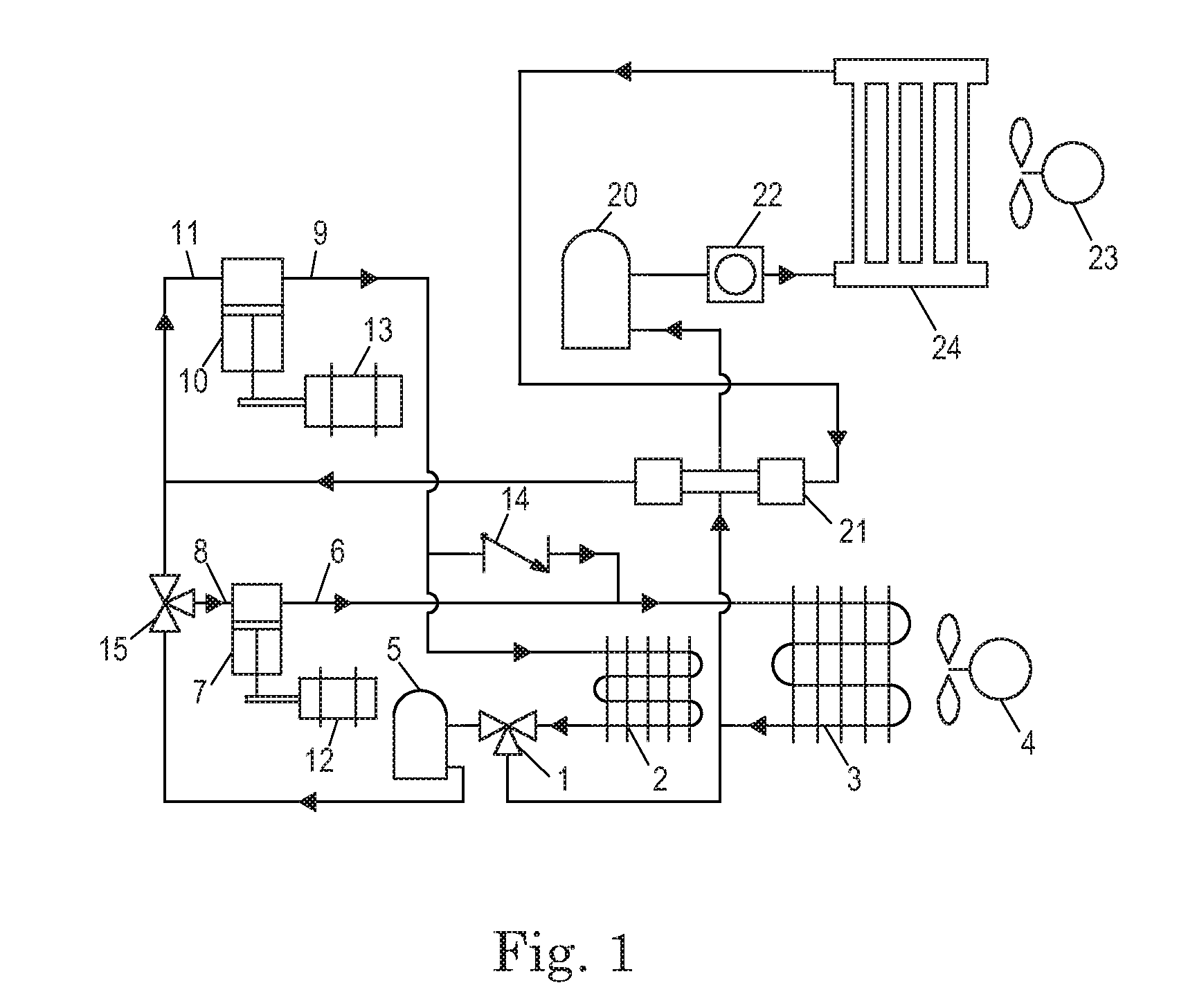
[0130]A first embodiment of a High Ratio Mobile Electric HVAC System shown in FIG. 1 achieves an exceptionally high 26:1, turn-down ratio by operating two compressors in four different modes—primary only, secondary only, primary and secondary in series and, lastly, primary and secondary in parallel. The benefit of this high turn-down ratio and multi-compressor capability is that the capacity of the system can be closely and most efficiently matched to the wide-ranging heat load common to mobile vehicles operating in on-highway and no-idle conditions. Given the particular compressor selection of the first embodiment, Table 1 shows the range of capacities that are available in each mode.

TABLE 1Compressor & modeCapacity Range (btu / hr)Secondary only1,000-6,000 Primary only3,350-20,000Primary and Secondary in series4,000-22,000Primary and Secondary in parallel4,500-26,000

Intelligent control system 34 receives information from user interface 50, dynamic cell charge controller 26 and other...

second embodiment

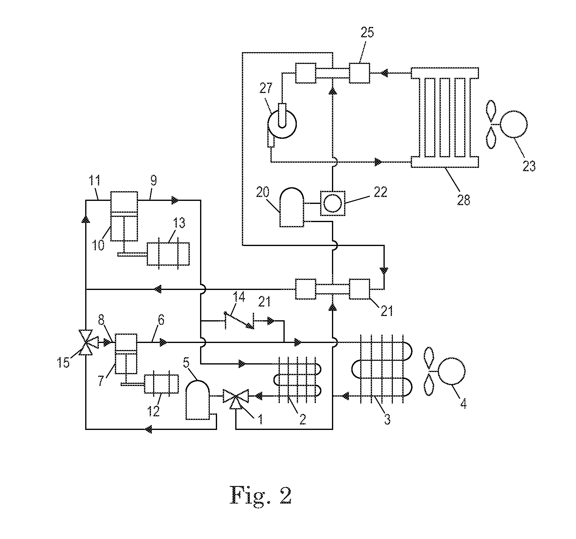
[0152]A second embodiment of a High Ratio Mobile Electric HVAC System is shown in FIG. 2 and incorporates a chilled water heat transfer loop to permit all refrigerant-containing components to be fully located outside the interior compartment. The direct expansion evaporator 24 of the first embodiment is replaced by a refrigerant-liquid heat exchanger 25 which is in fluid and thermal communication with the refrigerant circuit and with a circulating heat-transfer fluid. Similarly, the direct expansion evaporator 24 of the first embodiment is replaced by a liquid-air heat exchanger 28. Liquid pump 27, which is a centrifugal pump magnetically coupled to a permanent magnet variable-speed motor, circulates a heat transfer fluid such as a 40 / 60 mixture of propylene glycol and water though liquid-air heat exchanger 28 and through refrigerant liquid heat exchanger 25. The thermal effect is that heat from the air of an interior compartment, circulated by cooling circuit fan 23, enters the hea...

third embodiment

[0155]FIG. 3 shows a third embodiment of a High Ratio Mobile Electric HVAC System incorporating three compressors—a primary, a secondary and a tertiary compressor to achieve a stepless turn-down ratio of 258:1. As with the first embodiment, compressors may operate in parallel or series modes. Three compressors offer a much greater number of potential combinations than two compressors and offer a larger turn-down ratio covering a stepless capacity range which is 10× greater. In addition to running the compressors singly, in series and in parallel, three compressor offers the further possibility of running a combination of parallel and series. For example, two compressors in series and running that in parallel with the third compressor. The main governing factors determining what combinations are beneficial will be the compression ratio and the range of the load. One possible compressor capacity selection is shown in Table 3.

TABLE 3Compressor & modeCapacity Range (btu / hr)Tertiary only...


PUM


Abstract

An energy efficient and highly versatile electrically-powered air conditioning and heating system for mobile vehicles. Multiple variable-speed compressors operate in series and parallel modes giving an exceptionally wide range of operating capacity making the system suitable for combined on-highway and no-idle use in trucks. In series mode, the single-stage compressors function like a two-stage compressors for increased energy efficiency. A unique power control and storage system has multi-voltage input and output capability without the use of DC-DC or DC-AC converters. A battery management system is incorporated which is compatible with all advanced battery technologies and offers cell-level charge and discharge control.

Description

FEDERALLY SPONSORED RESEARCH[0001]NoneSEQUENCE LISTING OR PROGRAM[0002]NoneBACKGROUND[0003]1. Field[0004]This application relates to a predominately electrically powered HVAC system for mobile vehicles, and specifically to such a system using two separately controlled compressors.[0005]2. Prior Art[0006]Being alert and well-rested is important for the safety of truck drivers and others who share the road with them. Regulations in the United States and elsewhere limit the number of hours that a driver can be behind the wheel without an extended rest break. To comply with these regulations and avoid making side trips to costly and out-of-the-way motels, it is common practice for drivers to sleep in their trucks. Heavy duty trucks designed specifically for long haul operation, commonly known as Class 8 trucks in the U.S., have sleeping accommodations built into the driver's cab for this purpose.[0007]To ensure that the driver gets a restful sleep, it is often necessary to cool or heat ...

Claims


Application Information

Patent Timeline
IPC IPC(8): F25B49/00F25B41/00B60H3/00F25B1/10F25B49/02
CPCB60H1/3226B60H1/00378F25B1/10F25B27/00F25B2400/075
Inventor ALSTON, GERALD ALLEN
Owner ALSTON GERALD ALLEN
Learn More