
Deposition from ionic liquids

a technology of ionic liquid and ionic liquid, which is applied in the direction of liquid/solution decomposition chemical coating, conductive materials, metal/alloy conductors, etc., can solve the problems of affecting the nucleation of copper onto the barrier layer, affecting and affecting etc., to achieve the effect of improving the solubility of source materials and improving the nucleation density of depositing materials

Inactive Publication Date: 2011-11-03
KATHOLIEKE UNIV LEUVEN
View PDF10 Cites 15 Cited by
  • Summary
  • Abstract
  • Description
  • Claims
  • Application Information

AI Technical Summary

Benefits of technology

[0017]One way to directly deposit copper onto tantalum based barrier layers would involve transferring a substrate to a transfer module (in which the pressure is of the order of 10−8 Pa) through a load-lock. From the transfer module, the substrate is transferred to a deposition chamber where the deposition of the tantalum layer takes place (e.g. by means of Physical Vapor Deposition (PVD) at a base pressure of the order of 10−8 Pa). After the deposition of the tantalum layer, the substrate is transferred back to the transfer module and subsequently transferred to a second deposition chamber (pressure below 10−4 Pa) where the substrate is brought into contact with the ionic liquid and the deposition of metallic or semiconducting species from the ionic liquid onto the substrate takes place. Prior to this deposition process, the ionic liquid is subjected to a vacuum step (with a pressure below 10−4 Pa) in order to remove oxygen and water, thus avoiding the oxidation of the tantalum.
[0023]The ionic liquid may or may not contain additives that improve the solubility of the source material.
[0024]The ionic liquid may or may not contain additives that improve the nucleation density of the depositing material.

Problems solved by technology

Besides, all metals when exposed to oxygen or water form a layer of physisorbed or chemisorbed oxygen or oxygen containing species that can be detrimental for obtaining high nucleation densities of the species to be deposited on the substrate.
Electrodeposition of copper from an aqueous plating solution directly onto Ta is not possible as Ta will spontaneously cover itself with an oxide (or hydroxide) layer when brought in contact with air or water.
This reaction layer gives rise to a substantial contact resistance and hampers the nucleation of copper onto the barrier layer.
The conformity and the thickness of the seed layer makes it difficult to fill the sub-32 nm vias without defects by copper deposition.
However, even at the low oxygen and water concentrations of a glove box (which for a very good glove box is at most 0.5 to 1 ppm of oxygen and water), the oxidation of tantalum is very fast and Ta will be covered with an oxide layer in a very short time.

Method used


Image

  • Deposition from ionic liquids
  • Deposition from ionic liquids
  • Deposition from ionic liquids

Examples


example 2

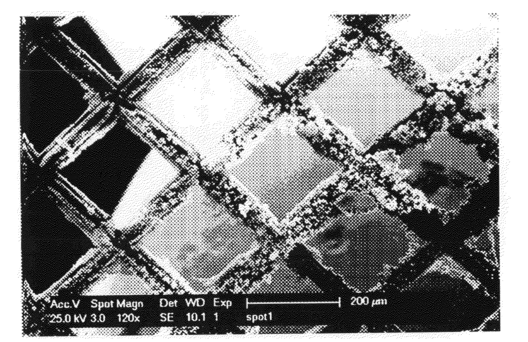
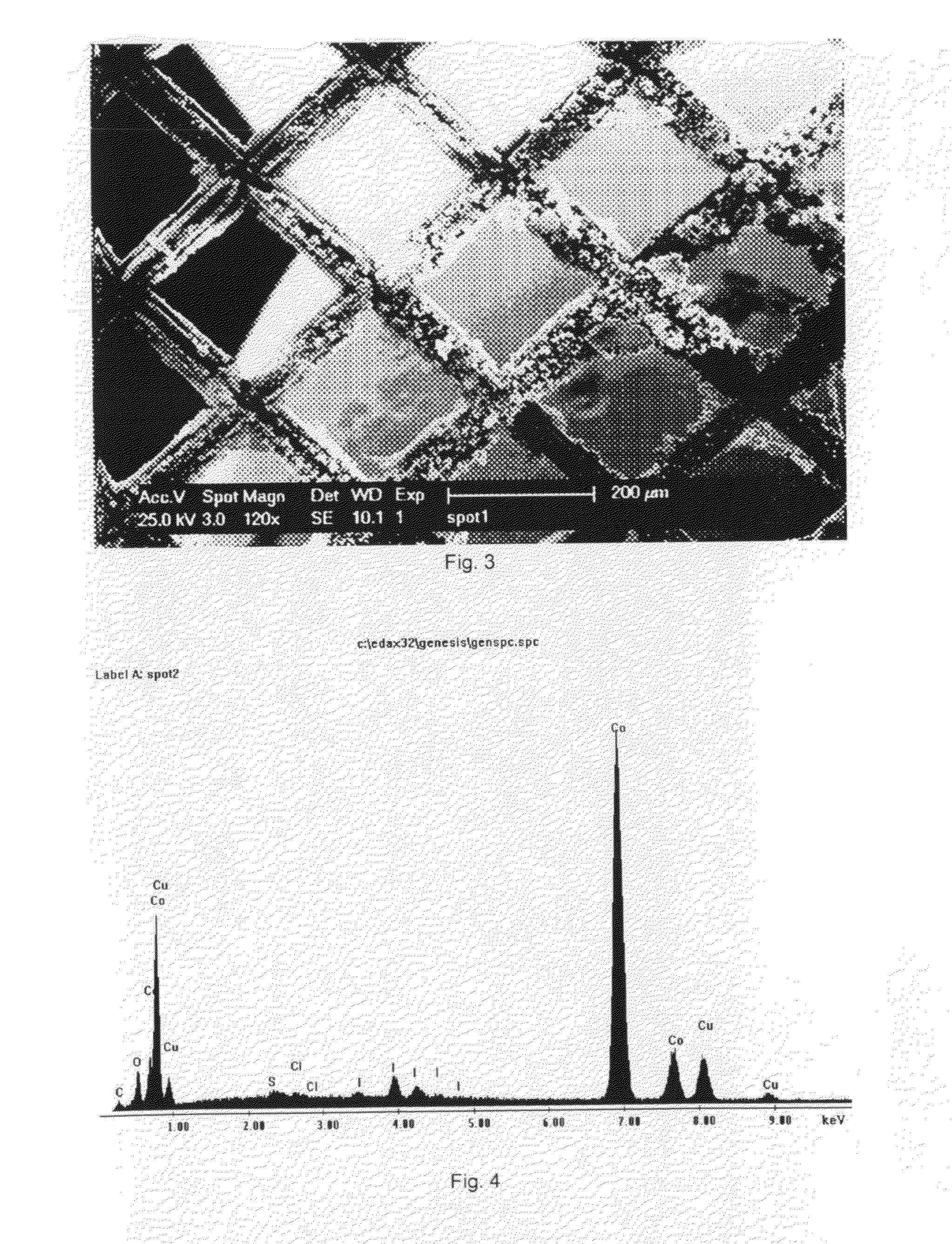
[0043]Deposits of cobalt were made in low vacuum using the e-SEM. The pressure was 3 torr of N2 and the acceleration voltage 25 kV. The substrate was a copper grid, whose pores are 200 micron wide. The solution that was used was 1-butyl-1-methylpyrrolidinium bis(trifluoromethylsulfonyl)imide in which 0.1 mol dm−3 of anhydrous Col2 was dissolved. Before use, this solution was dried at 120° C. under reduced pressure. The solution was contained in a copper crucible, in which a layer of cobalt had been electrodeposited from an aqueous CoCl2 bath, and this crucible served as counter electrode. It was heated by a Peltier element to about 90° C. A voltage of −3.00 V was hold between the working and counter electrode for about 2 hours. No reference electrode was used. After the deposition, dendritic cobalt deposits could be seen on the copper substrate (FIG. 3). The EDX analysis after placing the grid in acetone overnight to dissolve the ionic liquid and any adhering resin shows a very dist...

example 3

[0044]Cobalt was deposited in high vacuum on a Cu grid with 200 micron wide pores. The plating bath was [BMP][Tf2N] in which 0.2 mol dm−3 Co(Tf2N)2 was dissolved. Before use, the plating solution was placed inside a vacuum chamber and the pressure was reduced to 2 10−6 mbar. Next, the solution was placed inside the e-SEM and the pressure was reduced to 1 10−4 mbar. During the electrodeposition process, the pressure dropped further to 5.4 10−6 mbar. The plating solution was held in a copper crucible that was heated to 90° C. This crucible also served as counter electrode, no reference electrode was used. A voltage of 2 V was applied between the anode and cathode. After 90 minutes, a deposit had formed on the Cu-grid (FIG. 5). The EDX analysis after placing the grid in acetone overnight to dissolve the ionic liquid shows clear cobalt peaks (FIG. 6).

example 4

[0045]Copper was deposited in high vacuum on a Au grid with pore sizes of 7.5 micron wide. The plating bath was 1-butyl-1-methylpyrrolidinium bis(trifluoromethylsulfonyl)imide in which 0.2 mol dm−3 of copper bis(trifluoromethylsulfonyl)imide was dissolved. Before use, the plating solution was placed inside a vacuum chamber and the pressure was reduced to 2 10−6 mbar. Next, the solution was placed inside the e-SEM and the pressure was reduced to 1 10−4 mbar. During the electrodeposition process, the pressure dropped further to 2 10−6 mbar. The plating solution was held in a copper crucible that was heated to 90° C. This crucible also served as counter electrode, no reference electrode was used. A voltage of 2 V was applied between the anode and cathode. After 3 hours, a smooth deposit had formed (FIG. 7). The EDX analysis after placing the grid in acetone overnight to dissolve the ionic liquid shows a clear copper peak (FIG. 8).


PUM

PropertyMeasurementUnit
atmospheric pressureaaaaaaaaaa
pressureaaaaaaaaaa
vapour pressureaaaaaaaaaa

Abstract

A method to electrodeposit or electroless deposit material onto substrates from ionic liquids in vacuum or in a protective atmosphere after exposing the ionic liquid to vacuum and the resulting material. According to the invention, dense layers, free of unwanted components, can be produced in vacuum or in a protective atmosphere after exposing the ionic liquid to vacuum.

Description

BACKGROUND OF THE INVENTION[0001]1. Field of the Invention[0002]The present invention relates in general to electrodeposition or electroless deposition methods of metals or semiconductors on substrates from ionic liquids.[0003]2. Description of the Prior Art[0004]The electrodeposition of metals from ionic liquids is well known and is discussed in various publications (Electrochemical aspects of ionic liquids, H. Ohno (editor), Wiley Interscience, Tokyo (2005) and references therein) and in the patent literature (U.S. Pat. No. 6,573,405, Ionic liquids, from Abbott et al., U.S. Pat. No. 7,196,221, Ionic liquids and their use, from Abbott et al., WO2006 / 053362 A2, Method for depositing layers from ionic liquids, from Plansee et al., WO2006 / 061081 A2, Electrochemical deposition of tantalum and / or copper in ionic liquids, from Welz-Biermann et al., WO2006 / 074523 A1, Recovery of metals, from Houchin et al.[0005]The interest in electrodeposition and (to a lesser extent) electroless deposit...

Claims


Application Information

Patent Timeline
Patent Type & Authority Applications(United States)
IPC IPC(8): B05D5/12C25D5/00H01L21/20H01B1/02H01B1/06
CPCC23C18/31C25D3/665C25D5/34C23C18/40
Inventor FRANSAER, JAN
Owner KATHOLIEKE UNIV LEUVEN
Learn More