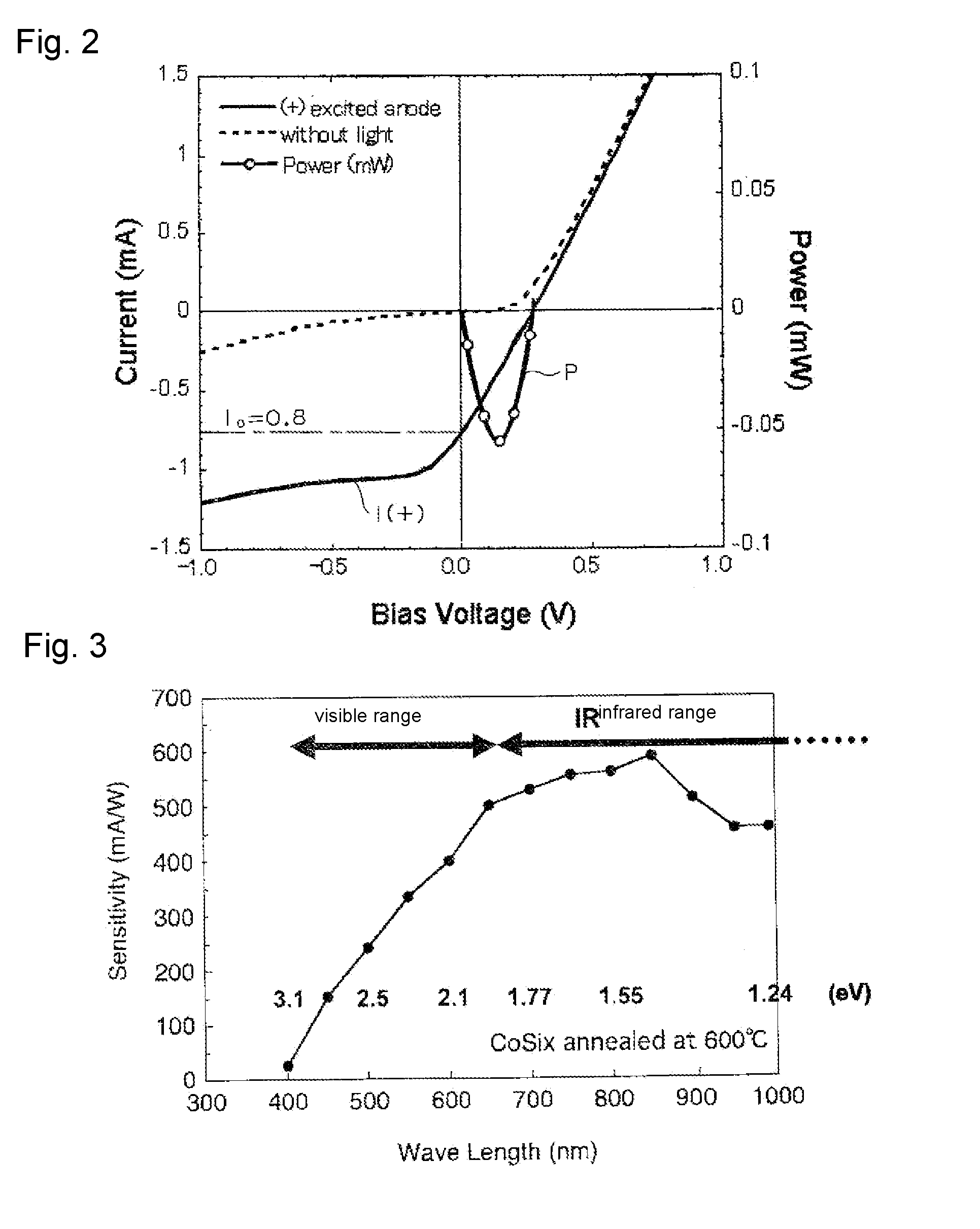
[0035]According to the invention of claim 1 and claim 7, photoelectric conversion of light having wide wavelength bands, from the
visible range to the
infrared range, can be performed in a manner independent on band gaps of materials of the substrate, such as
silicon, at ordinary temperature without using harmful substances. Therefore, in the case where the thin film photoelectric conversion device is used as a light detecting sensor, its excellent sensitivity characteristic makes it possible to detect a wide range of light. Further, in the case where the thin film photoelectric conversion device is used as a
solar cell, it is possible to perform photoelectric conversion of a wide range of
sunlight to utilize it as
electric power, and in particular when the
sky is cloudy, it is possible to utilize, as
electric power, about twice more
solar energy than that utilized in the case of solar cells using p-n junction Si-based photoelectric conversion devices. Furthermore, by performing photoelectric conversion of
infrared light scattered from the
atmosphere after
sunset, day / night power generation is expected. As the photoelectric conversion of the scattered infrared light is performed before the scattered infrared light is converted into heat, this is expected as a measure against global warning, as well.
[0036]The present invention is not for performing photoelectric conversion of light which transmits inside the substrate, but for performing photoelectric conversion at the surface of the substrate, and therefore, light loss is small and high sensitivity photo-induced current can be obtained.
[0037]Further, as photocarriers diffuse along the surface of the substrate, high speed photo-induced carriers with
diffusion speed of about 107 cm / s, which is comparable to the speed of compound semiconductors, are generated. Therefore, when used as a light detecting sensor, it is possible to realize a photoelectric conversion device which responds to an ultra-high speed
image sensor, or to optical modulation
waves in the GHz to THz band. As it is thin-film type, it is possible to use it as a surface-detecting CCD sensor which can be arrayed.
[0038]In addition, because majority carriers are generated at the interface of the barrier along the surface of the
semiconductor substrate and the
storage effect of minority carriers can be negligible, it becomes possible to reduce
noise in comparison to pn junction optical sensors, and when it is used for solar cells, coexistence of p-type and n-type carriers is suppressed and there is no decrease in the conversion efficiency caused by recombination of them.
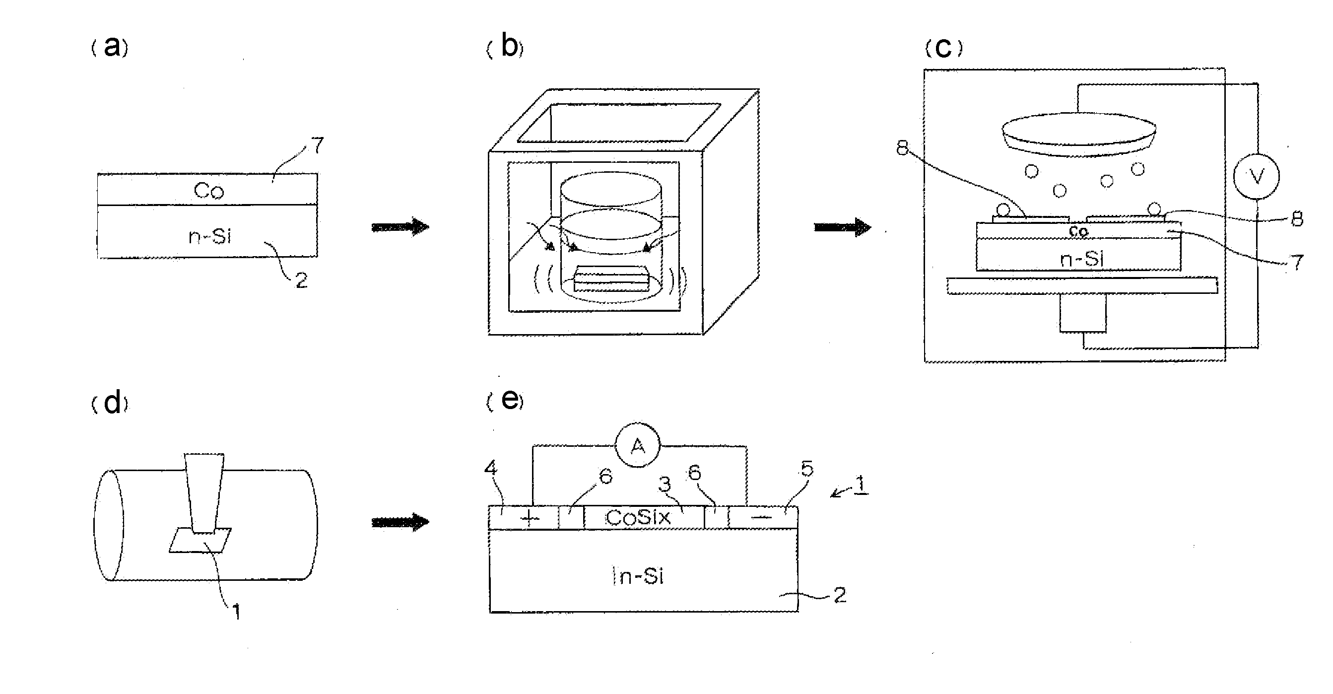
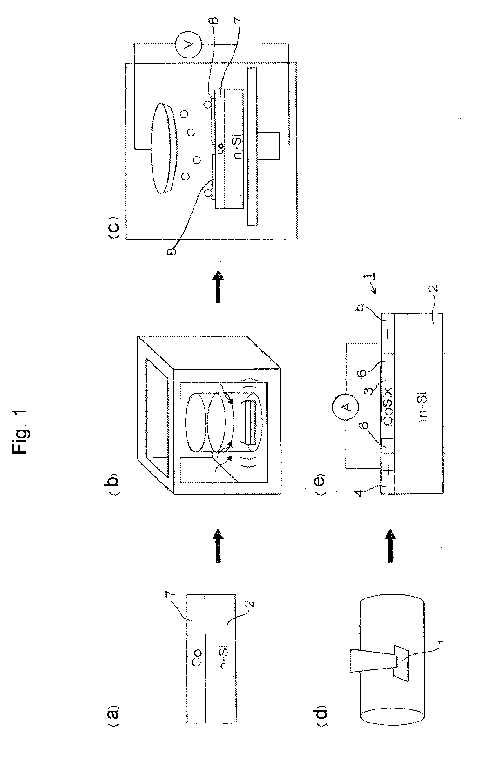
[0039]According to the invention of claim 7, in particular, the thin film photoelectric conversion device can be manufactured by a simple manufacturing process, only laminating the first
metal thin film layer and the second metal thin film layer on the substrate and annealing the substrate, and it can be manufactured by just using very small amount of scarce elements in the manufacturing process.
[0040]According to the invention of claim 2, the periodic structure and the
random structure, whose structures are different from each other, can be present in a mixed state in the same planar region by making differentiation between the heights of the second convex part and the first convex part from the substrate.
[0041]According to the invention of claim 3 and claim 8, generation of the photocarriers, high-efficiency generation of photocarriers caused by the enhancement of the photo-induced
electric field and output of the photo-induced current by the generated photocarriers can be realized only on the surface of one device.
[0042]In addition, as the photo-induced current can be generated by only using the conductive thin film layer and the metal
nanostructure on the surface of the substrate, the thickness can be reduced. When the thin film photoelectric conversion device is used for solar cells, it is possible to attach it to windows of buildings or automobiles, or housings for portable equipment such as mobile phones, and no restriction is applied to location to be attached.
[0043]Further, according to the invention of claim 4 and claim 8, the first
electrode ohmic connected to the conductive thin film layer and the metal
nanostructure can be formed by the process for forming the conductive thin film layer.
[0044]According to the invention of claim 5 and claim 9, the Si-based process for forming a
metal silicide can be used. In addition, the
metal silicide which forms the conductive thin film layer suppresses excessive
diffusion of the second metal, which is an
electrode-forming material, into the
silicon substrate, and can prevent oxidation of
silicon.
[0045]According to the invention of claim 6 and claim 10, the first metal and the second metal which is a
noble metal can be manufactured from very small amount of scarce elements because both of them are used only for forming the metal thin film
layers.
[0046]The first metal has a high
melting point, is excellent in
mechanical property at high temperature, and suitable as a material for the
metal silicide. In particular, in the case where the first metal is Co, the metal
silicide is CoSix used for an
electrode underlayer of a silicon device, and an existing process can be used. Further, the second metal is chemically stable, hard to combine with silicon, and easy to form a metal nanostructure.

