
Material for organic electroluminescent device and organic electroluminescent device using same

Active Publication Date: 2011-11-17
IDEMITSU KOSAN CO LTD
View PDF7 Cites 56 Cited by
  • Summary
  • Abstract
  • Description
  • Claims
  • Application Information

AI Technical Summary

Benefits of technology

[0019]According to the present invention, an organic EL device having a high efficiency in phosphorescent emission and a long lifetime and a material for an organic EL device which materializes the same can be provided.EMBODIMENTS FOR CARRYING OUT THE INVENTION
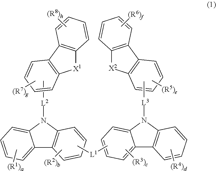
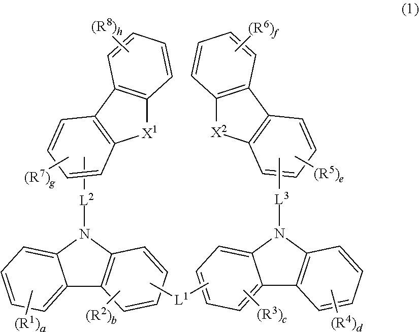
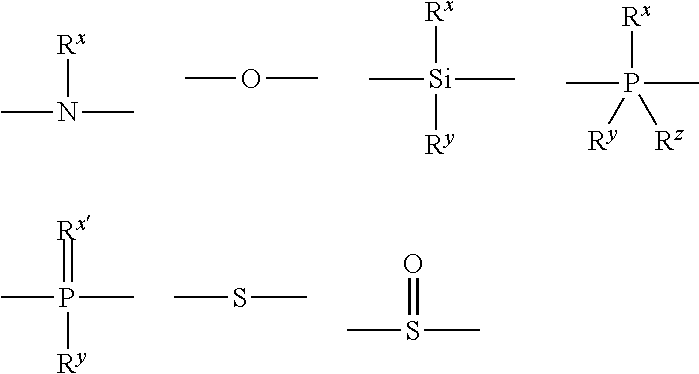
[0020]The material for an organic electroluminescence device according to the present invention is represented by Formula (1) shown below:(in Formula (1), X1 and X2 each are independently an oxygen atom or a sulfur atom, and they are not a sulfur atom at the same time (that is, X1 and X2 are an oxygen atom or one of them is an oxygen atom, and the other is a sulfur atom); R1 to R8 each represent independently an alkyl group having 1 to 20 carbon atoms, a cycloalkyl group having 3 to 20 ring carbon atoms, an alkoxy group having 1 to 20 carbon atoms, a cycloalkoxy group having 3 to 20 ring carbon atoms, an aryl group having 6 to 18 ring carbon atoms, an aryloxy group having 6 to 18 ring carbon atoms, a heteroaryl group having 5 to 18 ring atoms, an amino group, a silyl group, a fluoro group or a cyano group, and the above substituents R1 to R8 may be further substituted with the above substituents (hereinafter referred to as “the substituents R” as a whole); when R1 to R8 each are present in a plural number, they may be the same as or different from each other;a, d, f and h each represent independently an integer of any of 0 to 4, and b, c, e and g each represent independently an integer of any of 0 to 3; a sum of a to h is 6 or less;L1 represents a single bond, a divalent linkage group containing N, a divalent linkage group containing O, a divalent linkage group containing Si, a divalent linkage group containing P, a divalent linkage group containing S, an alkylene group having 1 to 20 carbon atoms, a cycloalkylene group having 3 to 20 ring carbon atoms, an arylene group having 6 to 18 ring carbon atoms, a heteroarylene group having 5 to 18 ring atoms, a divalent amino group or a divalent silyl group;L2 and L3 each represent independently a single bond, an alkylene group having 1 to 20 carbon atoms, a cycloalkylene group having 3 to 20 ring carbon atoms, an arylene group having 6 to 18 ring carbon atoms or a heteroarylene group having 5 to 18 ring atoms; L1 to L3 may be further substituted with any of the substituents R described above; provided that when L1 is an arylene group having 6 to 18 ring carbon atoms or a heteroarylene group having 5 to 18 ring atoms, a and d each represent independently an integer of any of 1 to 4).
[0021]In particular, bonding of a dibenzofranyl group or a dibenzothiophenyl group at an N-position (9-position) of a carbazolyl group directly or via a bonding group as shown in Formula (1) elevates a LUMO sequence of dibenzofrane or dibenzothiophene and makes it easy to inject electrons into a light emitting layer and the like in the organic EL device prepared by using the material for an organic electroluminescence device according to the present invention. This makes it possible to facilitate controlling the carrier balance, and the effects of the present invention are exerted well.
[0022]The alkyl group represented by R1 to R8 includes methyl, ethyl, propyl, isopropyl, n-butyl, s-butyl, isobutyl, t-butyl, n-pentyl, n-hexyl, n-heptyl, n-octyl, n-nonyl, n-decyl, n-undecyl, n-dodecyl, n-tridecyl, n-tetradecyl, n-pentadecyl, n-hexadecyl, n-heptadecyl, n-octadecyl, neopentyl, 1-methylpentyl, 2-methylpentyl, 1-pentylhexyl, 1-butylpentyl, 1-heptyloctyl, 3-methylpentyl and the like.
[0023]The examples of the cycloalkyl group represented by R1 to R8 include cyclopropyl, cyclobutyl, cyclopentyl, cyclohexyl, cycloheptyl, norbornyl, adamantyl and the like.
[0024]The alkoxy group represented by R1 to R8 includes methoxy, ethoxy, propoxy, butoxy, pentyloxy, hexyloxy and the like, and the groups having 3 or more carbon atoms may be linear, cyclic or branched.

Problems solved by technology

In blue color phosphorescent emission, however, it is difficult to achieve the high efficiency and the long lifetime, and a host material which achieves them is desired to be developed.

Method used


Image

  • Material for organic electroluminescent device and organic electroluminescent device using same
  • Material for organic electroluminescent device and organic electroluminescent device using same
  • Material for organic electroluminescent device and organic electroluminescent device using same

Examples


synthetic example 1

Synthesis of Compound (1)

(1) Synthesis of Compound (1-a):

[0182]

[0183]A three neck flask was charged with 40.1 g (240 mmol) of carbazole, 49.4 g (200 mmol) of 2-bromodibenzofuran, 3.81 g (20 mmol) of copper iodide, 84.91 g (400 mmol) of potassium phosphate, 7.21 ml (60 mmol) of trans-1,2-diaminocyclohexane and 100 ml of 1,4-dioxane under nitrogen atmosphere, and the mixture was refluxed for 24 hours. After finishing the reaction, the mixture was cooled down to room temperature and then diluted with 400 ml of toluene. The inorganic salts and the like were removed by filtration under reduced pressure, and the filtrate was passed through a short column of silica gel, and then concentrated. It was washed with an ethyl acetate / methanol mixed solvent to obtain a white solid matter (compound (1-a)). Amount: 54.0 g and yield: 81%

(2) Synthesis of Compound (1-b):

[0184]

[0185]A Kjeldahl flask was charged with 26.7 g (80 mmol) of the compound (1-a) and 160 ml of N,N-dimethylformamide under air to...

synthetic example 2

Synthesis of Compound (3)

(1) Synthesis of Compound (3-a):

[0192]

[0193]A three neck flask was charged with 41.2 g (100 mmol) of the compound (1-b), 23.0 g (140 mmol) of mesityl boronic acid, 200 ml of a barium hydroxide 2M aqueous solution and 50 ml of 1,2-dimethoxyethane under nitrogen atmosphere, and 3.47 g (3 mmol) of teterakis(triphenylphosphine)palladium was added to the above mixed solution, followed by refluxing the solution for 8 hours.

[0194]After finishing the reaction, the solution was cooled down to room temperature, and then the solution was extracted with toluene by means of a separating funnel. The extract was dried on anhydrous magnesium sulfate, filtrated and concentrated, and then the concentrate was purified by silica gel chromatography (toluene:hexane=3:7). This was recrystallized from hexane to obtain a white solid matter (compound (3-a)). Amount: 15.3 g and yield: 34%

(2) Synthesis of Compound (3)

[0195]

[0196]A compound (3) was synthesized by the same method as in t...

synthetic example 3

Synthesis of Compound (36)

[0197]

[0198]A three neck flask was charged with 7.13 g (14.4 mmol) of the compound (3-c), 1.42 g (6 mmol) of 1,3-dibromobenzene, 12 ml of a sodium carbonate 2M aqueous solution, 12 ml of 1,2-dimethoxyethane and 12 ml of toluene under nitrogen atmosphere, and 0.35 g (0.3 mmol) of teterakis(triphenylphosphine)-palladium was added to the above mixed solution, followed by refluxing the solution for 8 hours.

[0199]After finishing the reaction, the solution was cooled down to room temperature, and then the sample solution was transferred into a separating funnel and extracted several times with toluene. The extract was dried on anhydrous magnesium sulfate, then filtrated and concentrated, and the concentrate was purified by silica gel chromatography to obtain a white solid matter (compound (36)). Amount: 4.3 g and yield: 73%.

[0200]The above compounds were subjected to measurement of FD / MS and identified by an agreement of the theoretical values of the molecular we...


PUM


Abstract

The present invention provides a material for an organic electroluminescence device having a specific structure in which a dibennzofuranyl group or a dibenzothiophenyl group is bonded at an N-position (9-position) of a carbazolyl group and an organic electroluminescence device which is provided with one or more organic thin film layers including a light emitting layer between a cathode and an anode and in which at least one layer of the organic thin film layers described above contains the material for an organic electroluminescence device according to the present invention.

Description

BACKGROUND OF THE INVENTION[0001]1. Technical Field[0002]The present invention relates to a material for an organic electroluminescence device and an organic electroluminescence device prepared by using the same.[0003]2. Background Art[0004]An organic electroluminescence device (hereinafter “electroluminescence” shall be abbreviated as EL) is a spontaneous light emitting device making use of the principle that a fluorescent substance or a phosphorescent substance emits light by recombination energy of holes injected from an anode and electrons injected from a cathode by applying an electric field. Since a laminate type organic EL device operated at a low voltage was reported, researches on organic EL devices comprising organic materials as structural materials have actively been carried out. In the above laminate type device, tris(8-quinolinolate)aluminum is used for the light emitting layer, and a tetraphenyldiamine derivative is used for the hole transporting layer. The advantages...

Claims


Application Information

Patent Timeline
IPC IPC(8): H01L51/54C07D407/14C07D407/10
CPCC07D209/86C07D403/10C07D405/04C09K11/06C09K2211/1029C09K2211/1044C09K2211/1059C09K2211/1074C09K2211/1092C09K2211/185H05B33/14H05B33/20C07D405/14C09K11/025H10K85/649H10K50/11H10K85/342H10K85/6572H10K85/6574H10K50/12H10K50/15H10K50/171H10K85/6576H10K2101/10C09K2211/1007
Inventor NUMATA, MASAKINAGASHIMA, HIDEAKI
Owner IDEMITSU KOSAN CO LTD
Learn More