Microfluidic system and methods for highly selective droplet fusion

Active Publication Date: 2012-05-03
UNIVERSITY OF STRASBOURG +1
View PDF1 Cites 53 Cited by
  • Summary
  • Abstract
  • Description
  • Claims
  • Application Information

AI Technical Summary

Benefits of technology

[0030]In one exemplary embodiment, the first set of droplets contains a lower concentration of surfactant at the interface than the second set of droplets. In one non-limiting example, the concentration of surfactant in the carrier oil used to produce the first set of droplets is less than 3% and the concentration in the second set of droplets is greater than 3%, preferably greater than 4%. In another exemplary embodiment, the first and second set of droplets contain the same surfactant. In another exemplary embodiment, the first and second droplets contain different surfactants. The present invention is not limited by the type of surfactant or carrier oil used. The type of surfactant to be used will depend on the surfactant's effectiveness in stabilizing the interface of droplets, as well as in facilitating fusion of the first and second sets of droplets, as well as the surfactant's compatibility with any reactants contained within the first and second droplet pairs. One of ordinary skill in the art will be able to select the appropriate surfactant and carrier oil based on the desired properties of the droplets and reaction conditions used. In additions, the present invention provides a system by which different surfactants and surfactant combinations can be assessed for their effectiveness in the methods of the present invention.

Problems solved by technology

This technique enables the reliable fusion of droplets, which are generated on a microfluidic device—but not fully stabilized by surfactant—with surfactant-stabilized droplets in microfluidic channels.

Method used


Image

  • Microfluidic system and methods for highly selective droplet fusion
  • Microfluidic system and methods for highly selective droplet fusion
  • Microfluidic system and methods for highly selective droplet fusion

Examples


example 1

Experimental Methods

Microfluidics Device Fabrication and Running

[0181]Rectangular microfluidic channels were fabricated using soft lithography (Xia and Whitesides, 2008) by pouring poly(dimethylsiloxane) (PDMS, Sylgard 184, Dow Corning Corp.) onto a positive-relief silicon wafer (SILTRONIX) patterned with SU-8 photoresist (Microchem Corp). Curing agent was added to PDMS base to a final concentration of 10% (w / w), degassed and poured over the mould for crosslinking at 65° C. for 12 hours. The structured PDMS layer was peeled off the mould and the inlet and outlet holes were punched with a 0.75 mm-diameter Harris Uni-Core biopsy punch (Electron Microscopy Sciences). The microchannels were sealed by bonding the PDMS to glass using an oxygen plasma (PlasmaPrep 2 plasma oven; GaLa Instrumente GmbH). The channels were treated with surface coating agent (Aquapel, PPG Industries) to make it hydrophobic and subsequently flushed with nitrogen. Fluorinated oil FC40 (3M) containing different co...

example 2

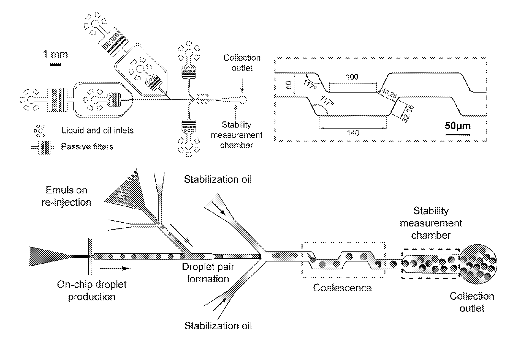
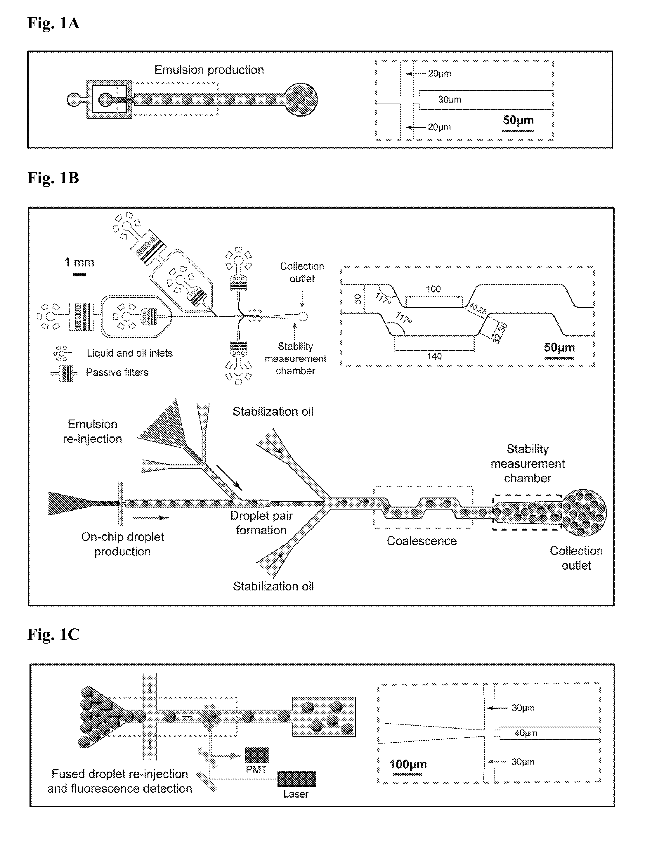
[0205]The inventors herein disclose a system for passive droplet separation using hydrodynamics, allowing fast and efficient fractionation of droplets with a difference in volume of as small as 2.33-fold (corresponding to a 1.33-fold difference in diameter of spherical droplets). The utility of this system was demonstrated by combining this system with the passive droplet fusion system of the invention to create an integrated microfluidic device allowing the preparation of highly monodisperse pairwise fused droplets. The reliability of the system was confirmed by performing fluorescent analysis of fused and size-fractionated droplets after collection off-chip and reinjection.

[0206]To develop the passive droplet separation system, firstly two types of droplets were mixed on the same microfluidic chip and the droplets were analyzed after size-dependent sorting. The microfluidic chips, containing rectangular channels, were fabricated using standard soft lithography methods as described...

example 3

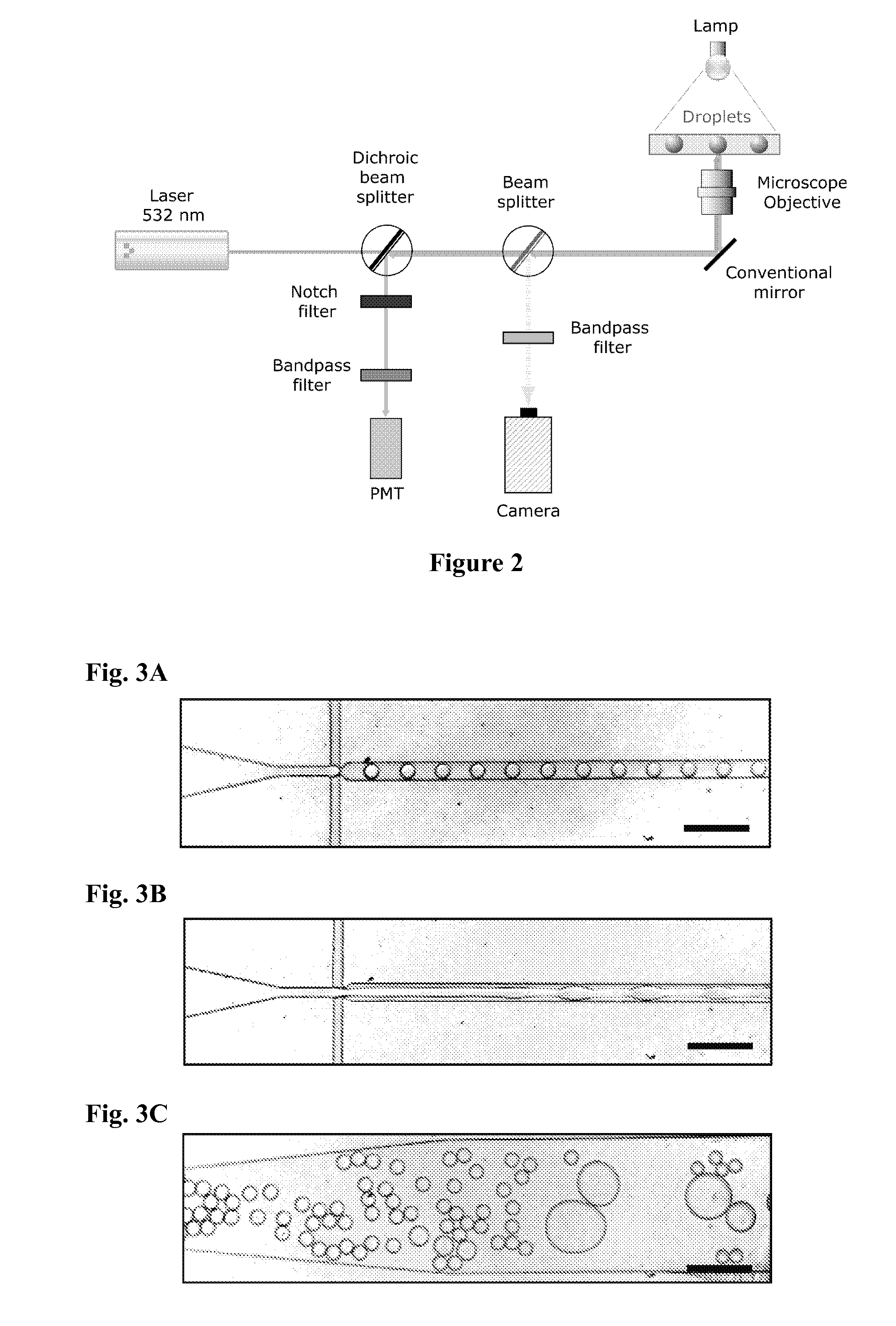
[0214]This example illustrates the selective coalescence of surfactant-stabilized droplets induced by the flow in microfluidic system. Individual surfactant-stabilized droplets from the emulsion were selectively coalesced with other droplets partially stabilized by the surfactant. The inventors showed selective pairwise and even multiple fusion events in highly controllable manner not feasible in prior art systems.

[0215]Material and Methods

[0216]Fabrication and Operation of Microfluidic Device

[0217]The microfluidic chip, containing rectangular channels 20 μm deep, was fabricated using standard soft lithography methods. Briefly, SU-8 2025 photoresist (Microchem Corp.) was poured onto a silicon wafer (Siltronix), patterned by UV exposure (MJB3 mask aligner, SUSS MicroTec) through a photolithography mask and subsequently developed with SU-8 developer (Microchem Corp). Curing agent was added to poly(dimethylsiloxane) PDMS base to a final concentration of 10% (w / w), degassed and poured o...


PUM

PropertyMeasurementUnit
lengthaaaaaaaaaa
widthaaaaaaaaaa
widthaaaaaaaaaa

Abstract

A method and chip for fusing droplets in a chip comprising (i) providing a first set of droplets which are partially or not stabilized by surfactant, (ii) providing a second set of droplets which are stabilized by surfactant, (iii) contacting each droplet of the first set with single or multiple droplets of the second set in a pairing module and (iv) fusing droplets of the first set with droplets of the second set through a droplet fusion module in which the droplets experience at least one acceleration and/or deceleration and/or reorientation and/or rearrangement in space and time.

Description

FIELD OF THE INVENTION[0001]The present invention is directed to systems and methods for reliable droplet fusion in a microfluidic system. The present invention also relates to micro fluidic systems and methods for fast and efficient size-dependent separation of droplets using hydrodynamics.BACKGROUND OF THE INVENTION[0002]All but the simplest reactions and assays require multiple steps where new reagents are added between steps. In microtitre-plate based systems, this is achieved by pipetting in new reagents at defined times. However, even using sophisticated (and expensive) robotic liquid-handling systems the throughput is little more than one per second. The quest for higher throughput is, of necessity, driving the development of ever smaller reaction vessels. However, there is little scope to further reduce reaction volumes below the current minimum of 1-2 μl using microtitre plate technology.[0003]One option is to use microdroplets in water-in-oil emulsions as microreactors: th...

Claims


Application Information

Patent Timeline
Patent Type & Authority Applications(United States)
IPC IPC(8): C08K5/17C08K5/06B01L3/00F15D1/00
CPCB01F3/0807B01F5/0646B01F5/0647B01F13/0062B01F13/0071B01J19/0093Y10T137/0318B01J2219/00889B01J2219/00891B01J2219/00909B01J2219/0097B01L3/502769B01J2219/0086B01F23/41B01F25/4331B01F25/433B01F33/3011B01F33/3021
Inventor MAZUTIS, LINAS
Owner UNIVERSITY OF STRASBOURG
Why Eureka
Try Eureka