Vanadium resistant coating system

a coating system and vanadium technology, applied in the field of coating systems, can solve the problems of shortening the life of the mgo, increasing the maintenance time of the turbine, and not completely preventing the mgo, so as to reduce the overall down time for repairs and increase the average length of time between shutdowns

Active Publication Date: 2012-05-24
GENERAL ELECTRIC CO
View PDF2 Cites 10 Cited by
  • Summary
  • Abstract
  • Description
  • Claims
  • Application Information

AI Technical Summary

Benefits of technology

[0010]An advantage of the coating system set forth herein is that it is survivable in an environment that includes vanadium oxides, such as is generated when inexpensive fuel oils, such as heavy fuel oils are combusted.
[0011]Another advantage of the coating system set forth herein is that, in one form, zirconium oxide is stabilized with a species that is less susceptible to attack from vanadium oxides than yttria, and hence is more stable than YSZ.
[0012]An advantage of a different form of the present invention is that a layer of zirconium oxide is stabilized with a species that is more susceptible to attack from vanadium oxides than yttria. In this form, the layer acts as a sacrificial layer as the zirconium oxide preferentially attacks it rather than the YSZ.
[0013]Because the coating system set forth herein is less susceptible to attack and spallation from vanadium oxides from the combustion of inexpensive fuels such as heavy fuel oil, the life expectancy of the substrates to which this coating system is applied is extended, and the operating life of the turbine components that include such coated substrates is also extended, so that average length of time between shutdown for repairs is increased, and the overall down time for repairs is decreased.

Problems solved by technology

Even though MgO is added as a fuel additive and acts as an inhibitor for reaction of vanadium species that forms an inert magnesium vanadate compound on or near the outer surface of the thermal barrier coating, MgO does not completely prevent the attack of YSZ thermal barrier coatings, as vanadium oxide can penetrate microcracks and porosity in the thermal barrier coatings, providing access not only to the YSZ thermal barrier coating, but also the underlying bond coat.
At these elevated temperatures, the substrate metal and the bond coat is subject to corrosion from the hot gases of combustion, which shortens their life.
As a result, the components such as combustors and turbine blades must be replaced in shorter intervals, which also means additional maintenance time for the turbine during which time it is not producing power.

Method used


Image

  • Vanadium resistant coating system
  • Vanadium resistant coating system
  • Vanadium resistant coating system

Examples


first embodiment

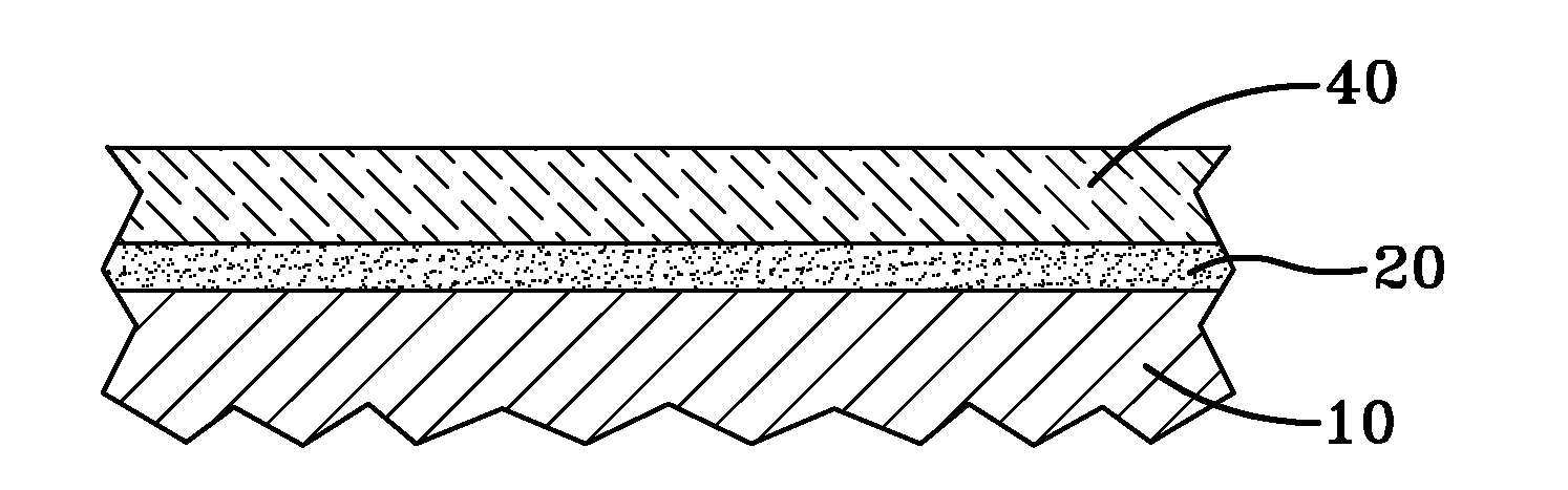
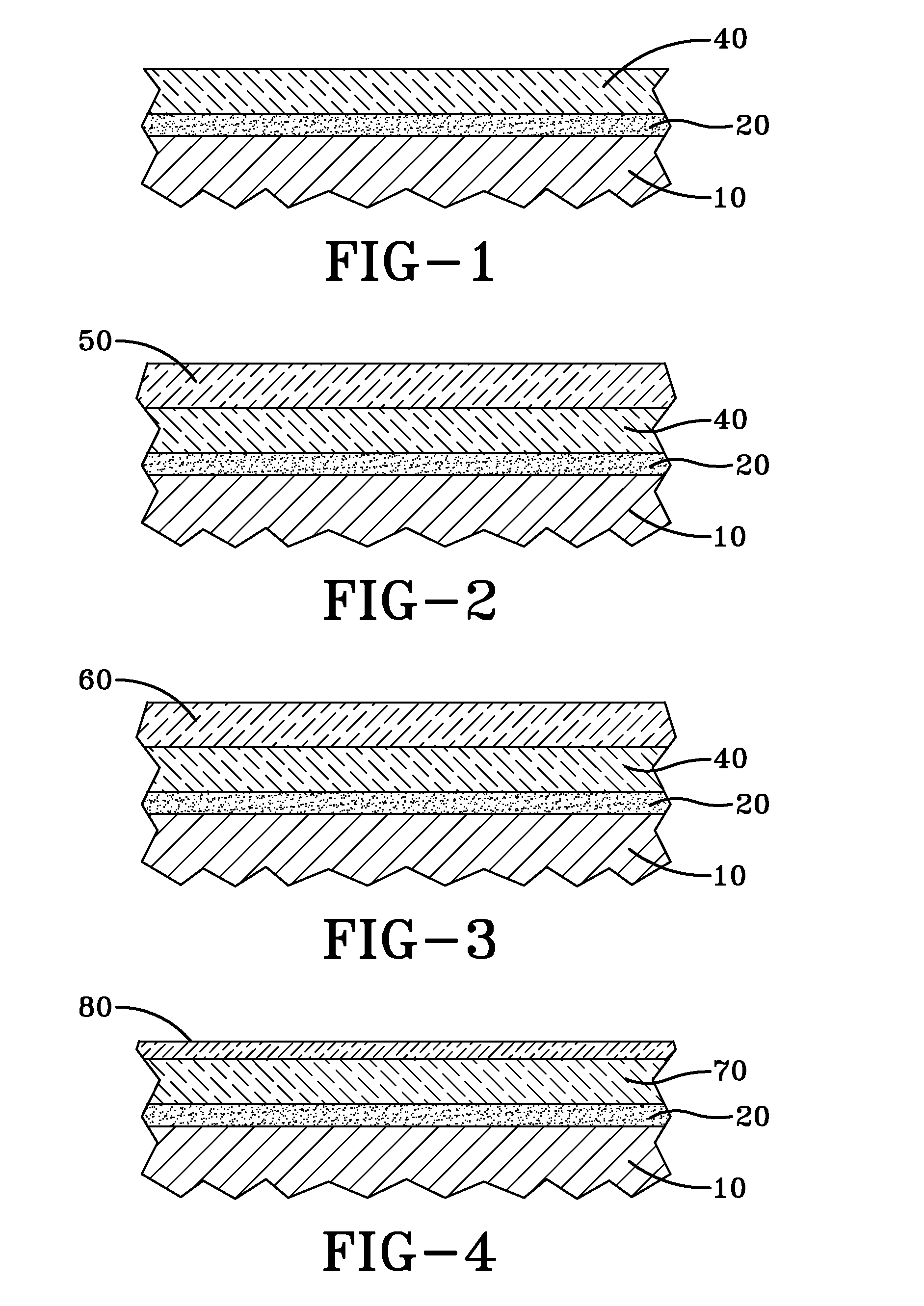
[0023]FIG. 1 represents the coating system. In this embodiment, as in all embodiments described herein, the coating system includes a substrate 10. While the substrate may be any metallic material capable of operating at high temperatures at or in excess of about 2000° F. (1093° C.), these high temperature metallic materials usually are superalloys, including but not limited to Ni-based superalloys, Co-based superalloys, Fe-based superalloys and superalloys that include combinations of Ni, Fe and Co. These superalloys are capable of operating at extended periods of time at temperatures at or in excess of 2000° F. (1093° C.) when appropriate steps are taken to protect the superalloy substrates from corrosion and / or oxidation.

[0024]In this first embodiment, immediately overlying substrate 10 is a bond coat 20. Bond coat 20 may be a MCrAlY applied over the metallic substrate, where M is a metal selected from the group consisting of Ni, Co, Fe and combinations thereof, although other bo...

second embodiment

[0027]the coating system is set forth in FIG. 2. This second coating system differs from the coating system set forth in FIG. 1 in that it includes an additional ceramic top coat 50 overlying ceramic coating 40. Substrate 10, bond coat 20, and ceramic coating 40 are substantially identical to these features as described in the embodiment set forth in FIG. 1. Additional ceramic top coat 50 overlies ceramic coating 40 but differs from the ceramic coating in that it further comprises a YSZ layer stabilized by 2-20 weight percent yttria. Such a YSZ layer includes porosity and cracks, typically in the form of microcracks, as are usually found in ceramic coatings applied by well-known thermal spray processes. However this YSZ coating differs from well-known YSZ layers in that the layer further includes zirconia stabilized by about 5-10 weight percent of a rare earth species having a larger atomic radius that Y3+. These rare earth species include a cation selected from the group consisting...

third embodiment

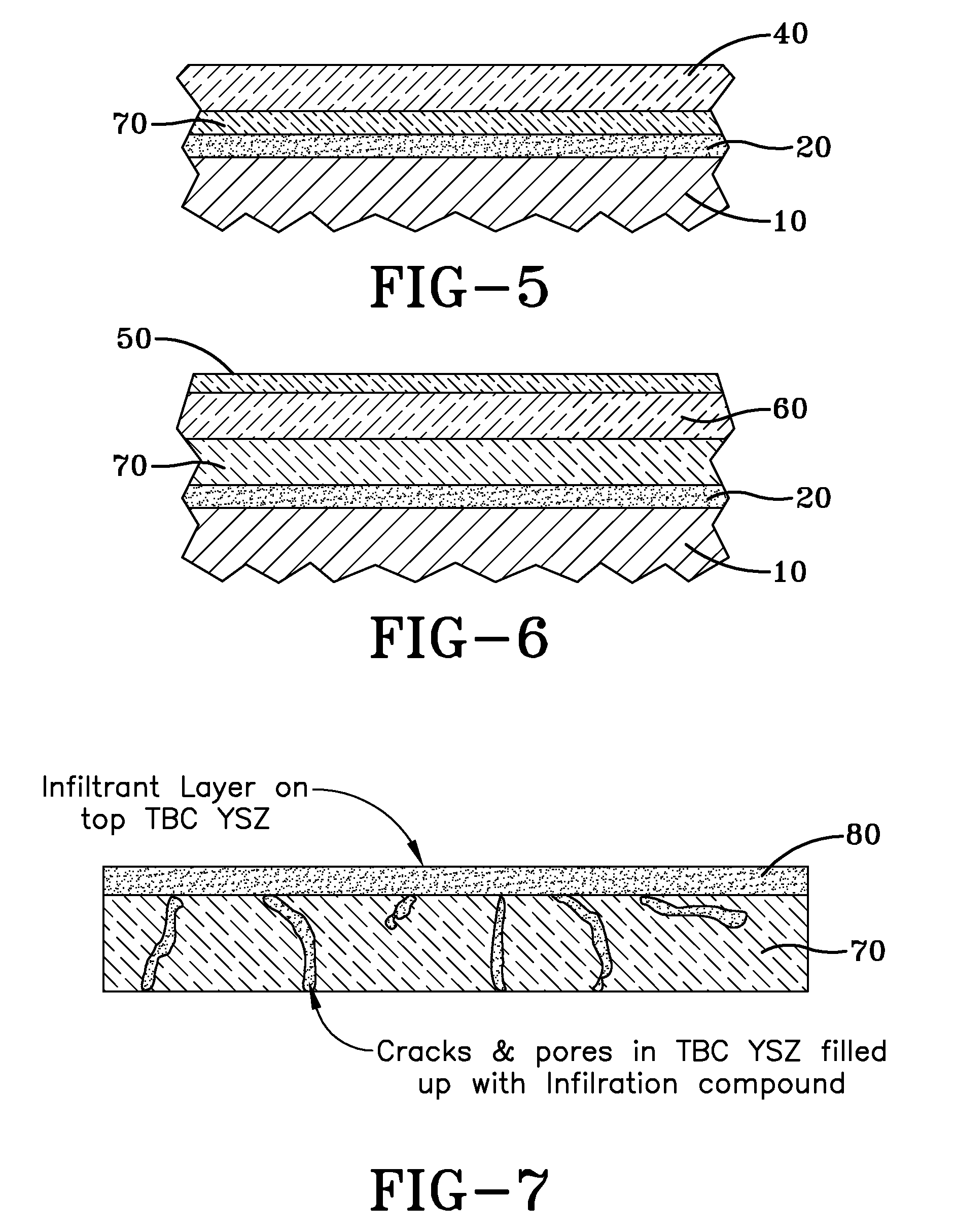
[0030]the coating system is set forth in FIG. 3. This third coating system differs from the coating system set forth in FIG. 2 in that it includes second ceramic coating 60 overlying first ceramic coating 40. Second ceramic layer 60 desirably is a pyrochlore composition or cerium stabilized zirconia (CSZ). Pyrochlores have a general formula of A2B2O7, where A is a metal having a valence of 2+ or 3+, for example, gadolinium, aluminum, cerium, lanthanum or yttrium, and B is a metal having a valence of 4+ or 5+, for example, hafnium, titanium, cerium or zirconium, where the sum of the valences of the A and B metals is 7. However, ceramic coating 40 is then relied on to provide further protection for the system, and the sacrificial nature of second ceramic layer 60 will have served its purpose in delaying first ceramic layer 40 from full exposure to the vanadium species.

[0031]Spalling could occur due to a number of mechanisms, including corrosive attack of the ceramic overcoats 40, 50, ...


PUM

PropertyMeasurementUnit
temperaturesaaaaaaaaaa
temperatureaaaaaaaaaa
thicknessaaaaaaaaaa

Abstract

A vanadium resistant coating system resistant to high temperature vanadium attack. The system comprises a high temperature superalloy substrate. A bond coat overlies the superalloy substrate. The bond coat may be applied in multiple layers. A ceramic coating overlies the bond coat. The ceramic coating further comprises a zirconium oxide stabilized by at least one cation selected from the group consisting of Yb3+, Lu3+, Sc3+ and Ce4+, in the amounts of about 5-10 weight percent. An overcoat may overlie the ceramic coating. The overcoat may be a sacrificial layer of YSZ infiltrated with cations having an atomic radius larger than Y3+. Alternatively, the overcoat may comprise zirconium oxide stabilized by Ce4+.

Description

FIELD OF THE INVENTION[0001]The present invention is directed to a coating system having improved corrosion resistance when exposed to the by-products of the combustion of heavy fuel oil, and more specifically, to a coating system applied to superalloys used in high temperature applications exposed to attack by vanadium species from the combustion of heavy fuel oil.BACKGROUND OF THE INVENTION[0002]Yttria-stabilized zirconia (YSZ) is a well known material used to improve the performance of metals used in high temperature metals. The YSZ is applied, typically by a high temperature thermal spray coating process, as a thermal barrier coating (TBC). The TBC increases the operating temperature of the high temperature substrate metal. In addition, a bond coat is applied between the TBC and the high temperature metal to reduce the thermal mismatch between the TBC and the high temperature metal, which improves the spallation resistance of the TBC. This thermal barrier coating system includes...

Claims


Application Information

Patent Timeline
Patent Type & Authority Applications(United States)
IPC IPC(8): B32B18/00B32B15/04
CPCC23C24/08Y02T50/67C23C28/321C23C28/3215Y10T428/12549C23C28/3455C23C28/36Y10T428/12611C23C28/345Y02T50/60
Inventor PABLA, SURINDER SINGHPAREEK, VINOD KUMARSANYAL, SUCHISMITAANAND, KRISHNAMURTHYBHATTACHARYA, PRAJINA
Owner GENERAL ELECTRIC CO
Why Eureka
Try Eureka