
Process for revamping an ammonia plant with nitrogen-based washing of a purge stream

Active Publication Date: 2012-06-07
CASALE SA
View PDF3 Cites 5 Cited by
  • Summary
  • Abstract
  • Description
  • Claims
  • Application Information

AI Technical Summary

Benefits of technology

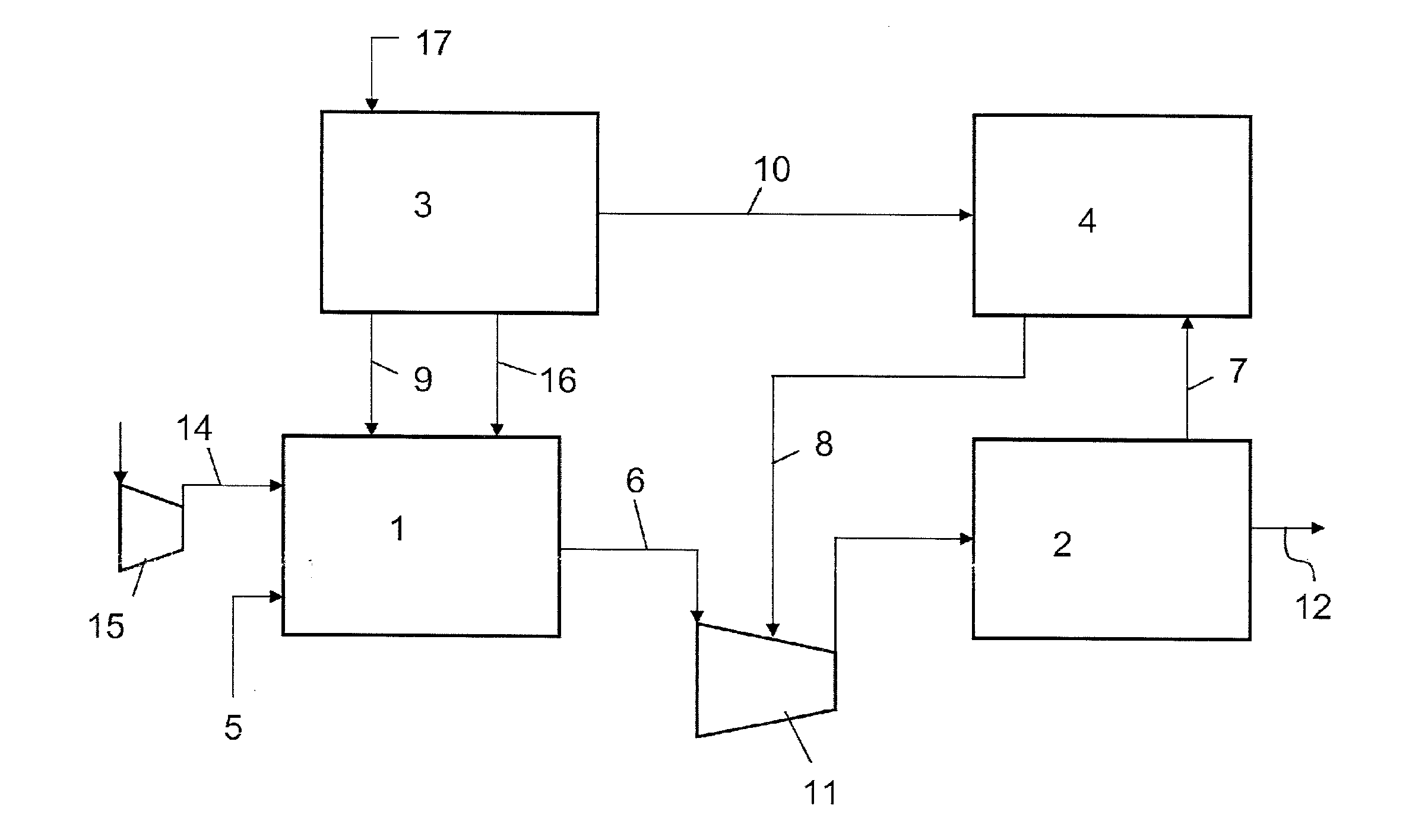
[0034]A basic advantage of the invention is that the nitrogen stream from the ASU is used to make the process more efficient, by recovering the hydrogen of the purge gas, not only to adjust the HN ratio of the syngas feed.
[0035]The invention allows to boost the capacity of the plant, reduces the flow rate increase through the whole front-end and related problems, including pressure drops and duty of the CO2-removal and methanation section. The front-end receives only the pure oxygen stream, necessary for boosting the reforming capacity, while the nitrogen stream, which would pass through the front end substantially as inert gas, is appropriately fed only to the purge gas recovery section, where it is required as one of the reagents to produce ammonia, and in order to establish the correct HN ratio of the make-up syngas.
[0036]The use of liquid nitrogen to recover the hydrogen contained in the purge gas, instead of injecting or using it directly in the front-end, has the advantage to require significant less investment cost; actually this washing / treating is accomplished on the purge gas that is typically ten times less than the make-up syngas flow rate fed to the synthesis loop. Another advantage is that the nitrogen is used to wash a stream, namely the purge gas or tail gas, containing a higher amount of inerts than the make-up syngas, and therefore the nitrogen washing of the purge is highly efficient.
[0037]The oxygen feed to the secondary reformer has further advantages. The load of the air compressor feeding the secondary reformer is reduced, because a portion of the oxygen necessary to the secondary reformer is now supplied by the ASU. This means that the capacity of the plant can be increased for a given size and output of the air compressor, without the need of a larger and more expensive compressor. In the revamping of an existing plant, the invention provides additional capability / operability of the existing air compressor in case of worse environmental conditions, capacity increase, possible use of the spare compressed air in other location of the ammonia plant. Feeding the existing air compressor with an oxygen-enriched air stream allows to obtain a greater reforming capacity with the same flow rate at inlet of the compressor, i.e. without the need to modify the compressor itself.
[0038]Feeding additional oxygen to the secondary reformer has also the advantage that the reforming capacity is substantially increased with no modification of the upstream primary reformer. This is a relevant advantage because, as stated above, boosting the primary reformer is generally not possible or expensive.
[0039]By separating the basic components of air (oxygen and nitrogen), the invention allows oxygen and nitrogen addition in optimum points of the plant. More oxygen is available where necessary, namely at the input of the secondary reformer, and nitrogen is fed only where necessary, that is to the ammonia synthesis loop.

Problems solved by technology

Retrofitting or boosting an ammonia plant poses a number of problems in connection with the increased flow rate.
The capacity of the primary reformer is closely related to the size and number of tubes of the reformer itself; the option of installing additional tubes is generally not possible or very limited; installing an additional pre-reformer is possible, but is expensive and gives an advantage of 10-15% only.
The options of installing new internals on the existing air compressor, or providing a further compressor in parallel to the existing one, are both expensive.
Installation of a booster, i.e. a pre-compressor disposed to raise the pressure at the intake of the main air compressor, is less expensive but also less effective.
An increased flow rate needs also to be accommodated through the various equipments of the front-end, e.g. CO2 removal unit, methanator, etc. . . . and this may require significant investment costs if any of these equipments needs to be modified.
The capacity of the syngas compressor is also a critical point and a potential bottleneck.
Installation of any booster or additional compressor is generally not accepted, because failure of any additional equipment may compromise the reliability of the whole plant and may cause severe damage to the main compressor.
It is usually preferred to replace the internals of the compressor and turbine, but this intervention is expensive.
Another problem is the possible accumulation of inert gases in the synthesis loop.
Accumulation of inert gases means an increased flow rate and reduced yield of conversion.
All the above problems are felt when an existing plant is revamped, but also when a new plant is designed, trying to increase the overall capability with regard to the size of the main items, such as reformers and compressors.

Method used


Image

  • Process for revamping an ammonia plant with nitrogen-based washing of a purge stream
  • Process for revamping an ammonia plant with nitrogen-based washing of a purge stream
  • Process for revamping an ammonia plant with nitrogen-based washing of a purge stream

Examples


example 1

[0060]The numerals in the following example relate to FIG. 1. A conventional ammonia plant is revamped by installation of the ASU 3 providing the oxygen stream 9 and the nitrogen stream 10 used to wash the purge gas. The following can be noted: the ammonia output (stream 12) is increased by 14% while air feed 14 to the air compressor decreases by 11%; the total oxygen feed to the secondary reformer however is increased by around 37%, as the air feed 14 contains 21% oxygen while the stream 9 is 95% oxygen. Table 1c discloses detailed composition of streams in FIG. 1 (revamped case).

TABLE 1a(base case)Stream591412Vapour Fraction1.00—1.000.08(mole)Temperature° F.76.5—333.53.0Pressurepsig630.80—493.1017.26Molar Flowlbmole / hr4185.0—5840.08791.3Mass Flowlb / hr69206.8—169153.9149716.3

TABLE 1b(revamped)Stream591412Vapour1.001.001.000Fraction(mole)Temperature° F.72.8104.0330.43.0Pressurepsig645.00522.14508.1517.26Molar Flowlbmole / hr4953.0618.05200.010085.1Mass Flowlb / hr81907.219947.8150616.51...

example 2

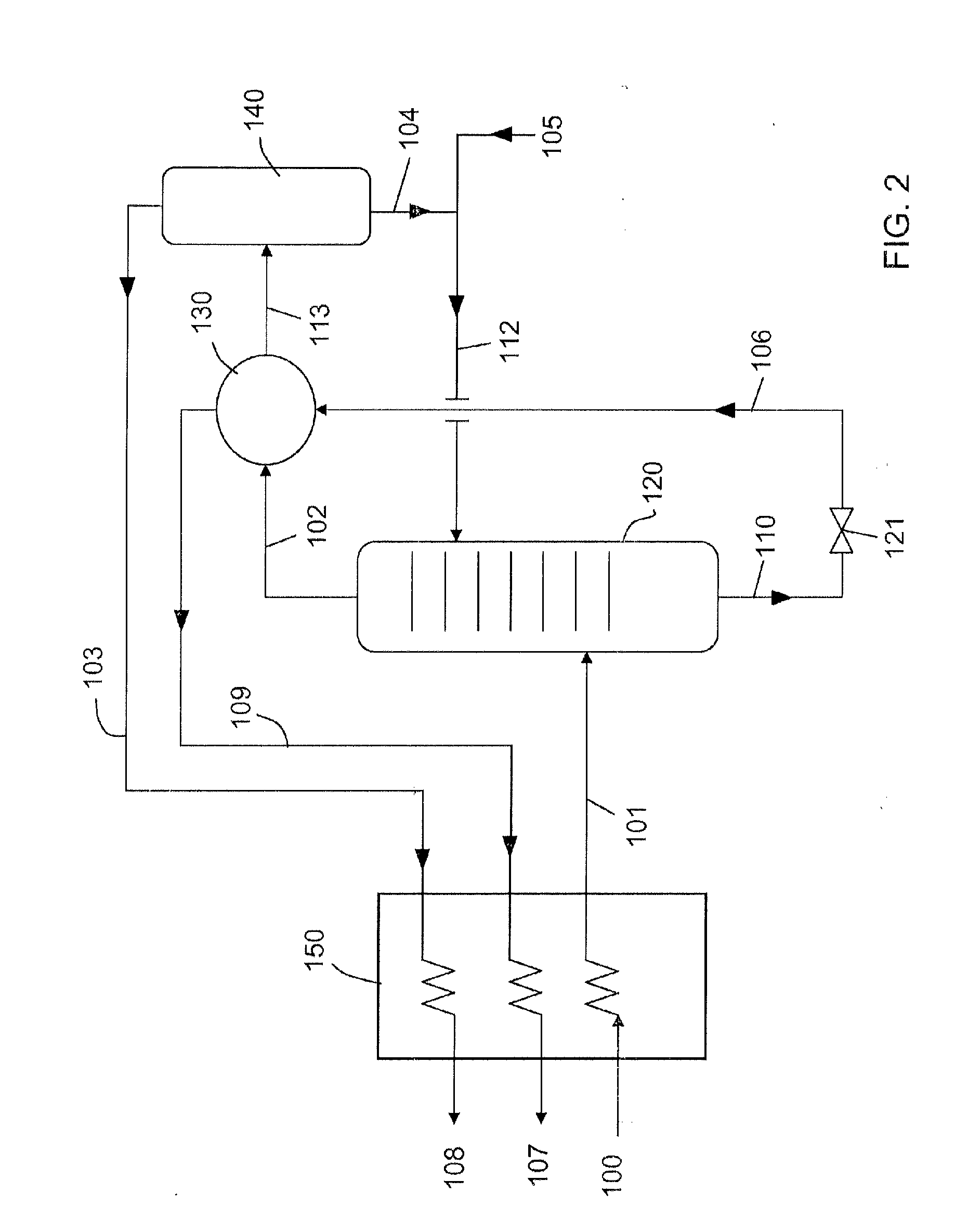
[0061]The following table 2 relates to a plant as in FIG. 2, where purge gas 100 containing around 66% hydrogen and 21.5% nitrogen, plus a 6.4% methane and 5.8% Argon, is treated in a cryogenic section obtaining a methane-free recycle stream 108, containing around 70% hydrogen and 28% nitrogen.

TABLE 2Stream100101102103104Vapour Fraction (mole)1.000.951.001.000.00Temperature° F.14.0−239.7−266.7−277.0−277.0Pressurepsig1976.671975.67900.00900.00900.00Molar Flowlbmole / hr1384.11384.11542.81278.1264.7Mass Flowlb / hr14884.814884.819336.312648.46687.9Composition% molH2  66.092%  66.092%  60.446%  70.245% 13.139%N221.586%21.586%37.589%28.541%81.272%CH46.473%6.473%0.001%—0.004%Ar5.848%5.848%1.964%1.214%5.585%Stream105106107108Vapour Fraction (mole)0.000.261.001.00Temperature° F.−240.0−294.4−22.0−44.0Pressurepsig900.0029.0128.01899.00Molar Flowlbmole / hr198.4304.5304.51278.1Mass Flowlb / hr5558.27794.97794.912648.4Composition% molH2—5.584%5.584%70.245%N2100.000%43.504%43.504%28.541%CH4—29.427%29.4...

example 3

[0062]The following table 3 relates to a plant as in FIG. 3, where tail gas 100a containing around 15% hydrogen and 48% nitrogen, is treated in the cryogenic section. The obtained recycle stream 108 contains around 42% hydrogen and 56% nitrogen.

TABLE 3Stream100a101102103104Vapour Fraction (mole)1.000.971.001.000.00Temperature° F.122.0−194.6−248.7−264.3−264.3Pressurepsig901.45900.00435.11435.11435.11Molar Flowlbmole / hr557.0557.0553.9170.0383.9Mass Flowlb / hr12585.512585.512962.92915.110047.8Composition% molH214.542%14.542%18.758%42.334%8.319%N248.474%48.474%79.002%56.492%88.970%CH425.314%25.314%0.009%0.002%0.012%Ar11.670%11.670%2.231%1.172%2.699%Stream105106107108Vapour Fraction (mole)0.000.431.001.00Temperature° F.−234.4−288.596.750.0Pressurepsig454.3326.1123.21433.66Molar Flowlbmole / hr44.1431.1431.1170.0Mass Flowlb / hr1235.110906.910906.92915.1Composition% molH2—2.096%2.096%42.334%N2100.000%50.582%50.582%56.492%CH40.000%32.704%32.704%0.002%Ar0.000%14.618%14.618%1.172%

[0063]In the abo...


PUM

PropertyMeasurementUnit
Molar densityaaaaaaaaaa
Fractionaaaaaaaaaa
Fractionaaaaaaaaaa

Abstract

A process and a plant for producing ammonia, where an ASU (3) delivers an oxygen stream and a nitrogen stream; the oxygen stream (9) is fed to the secondary reformer of a front-end reforming section (1); the nitrogen stream (10) is used to wash a purge gas or tail gas taken from the synthesis loop (2), preferably in a cryogenic section; a methane-free and inert-free gas stream is recovered and recycled to the synthesis loop (2) or at the suction of the main syngas compressor, to recover the hydrogen contained therein. A corresponding method for increasing the capacity of an ammonia plant, by providing the ASU and feeding the oxygen stream to the secondary reformer and the nitrogen stream to a suitable purge gas recovery unit.

Description

FIELD OF THE INVENTION[0001]The invention relates to improvements in a process and plant for producing ammonia by steam reforming of a hydrocarbon such as natural gas.PRIOR ART[0002]Ammonia is produced by catalytic reaction between hydrogen and nitrogen, in a high-pressure synthesis loop. It is known art to feed said high-pressure loop with a make-up synthesis gas mainly consisting of hydrogen (H2) and nitrogen (N2) in a suitable molar ratio, obtained by steam reforming of a hydrocarbon feedstock, usually natural gas (methane) or naphta.[0003]The syngas is obtained in a front-end section of the ammonia plant, comprising essentially a primary reformer, a secondary reformer, a cooling / shift converter, a CO2 separation section, a methanation section and a syngas compressor.[0004]The primary reformer converts steam and a feedstock of a desulphurized hydrocarbon, for example natural gas or substitute natural gas (SNG), into a mixture of carbon monoxide, carbon dioxide and hydrogen, by pa...

Claims


Application Information

Patent Timeline
IPC IPC(8): C01C1/04B23P6/00B01J19/00
CPCC01B3/025Y10T29/49718C01B13/0229C01B2203/025C01B2203/068C01B2210/0046C01C1/0405C01C1/0476C01C1/0482F25J3/0219F25J3/0276F25J3/04539F25J3/04587F25J2200/74F25J2205/30F25J2210/04F25J2210/20F25J2210/42F25J2270/02F25J2290/80C01B3/36Y02P20/52C01C1/04
Inventor PANZA, SERGIOMOREO, PIETROSTREPPAROLA, ELIO
Owner CASALE SA
Learn More