Substrate, manufacturing method of substrate, semiconductor element, and manufacturing method of semiconductor element

Inactive Publication Date: 2012-06-28
NEC CORP
View PDF0 Cites 94 Cited by
  • Summary
  • Abstract
  • Description
  • Claims
  • Application Information

AI Technical Summary

Benefits of technology

[0020]This invention is able to provide a high-quality, large-area graphene substrate which is directly usable for production of semiconductor devices, and a semiconductor device produced using such a graphene substrate.
[0021]This invention is als

Problems solved by technology

However, the graphene manufacturing methods as disclosed in Patent Documents 1 to 3 and other currently available techniques have problems as described below.
A first problem is that the substrate used for CVD growth of graphene cannot be used directly for production of elements.
A second problem resides in that conventional CVD grown graphene has much higher sheet resistance than an ideal graphene, and has very poor mobility.
This is attributable to the fact that many lattice defects are introduced in the graphene, structural breaks or wrinkles are generated, or a contaminant inhibiting electron transport adheres to

Method used


Image

  • Substrate, manufacturing method of substrate, semiconductor element, and manufacturing method of semiconductor element
  • Substrate, manufacturing method of substrate, semiconductor element, and manufacturing method of semiconductor element
  • Substrate, manufacturing method of substrate, semiconductor element, and manufacturing method of semiconductor element

Examples


working example 1

CVD Growth of Graphene Layer and Dependency on Metal Catalyst

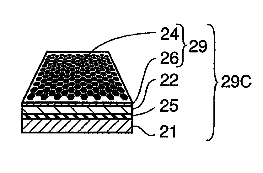
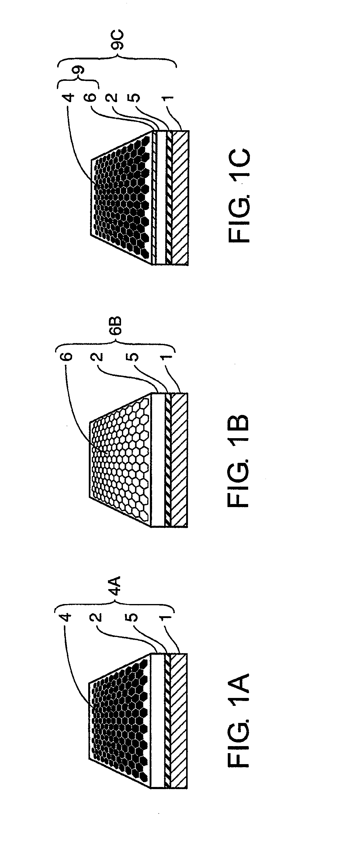
[0137]The graphene layer 24 and the graphene substrate 24A were fabricated according to the fabrication method shown in FIGS. 3A to 3E. A silicon substrate as the substrate 21 was thermally oxidized to form a silicon oxide layer (oxide layer 22), and then iron, nickel and copper as metal catalysts were sputtered to form a film, respectively. Using each of these metal catalysts, CVD growth of graphene was performed at a temperature of 1000° C., using methane as a carbon source. FIG. 4 represents a typical thermal profile before and after the CVD growth of graphene. The CVD growth was performed in the procedures as described below. The substrate comprising the metal catalyst film formed thereon was heated from room temperature to a CVD growth temperature under the flow of gas mixture of hydrogen and argon, and the CVD growth temperature was kept for about 10 to 60 minutes to age the metal catalysts. After that, flow of gas m...

working example 2

CVD Growth of Graphene Layer and Dependency on CVD Growth Conditions

[0138]Effects of CVD growth conditions on growth of graphene when the metal catalyst was nickel were examined. Examined growth parameters were temperature drop rate [° C. / min] after CVD growth, and methane concentration [% by volume] in gas mixture of argon, hydrogen and methane. The other CVD growth conditions including metal catalyst aging conditions and graphene growth temperature (1000° C.) were kept constant. Surface of grown graphene was evaluated with the use of an atomic force microscope, a scanning electron microscope or the like. Table 1 shows a relationship between temperature drop rate and methane concentration given to the growth of graphene, and summarizes features of graphene obtained under each condition. What is noticeable in the first place is that when the methane concentration was 0.25% by volume, little growth of graphene was observed no matter how much is the temperature drop rate, whereas when...

working example 3

Fabrication of Graphene Layer and Graphene Substrate

[0139]A graphene layer was formed on a comb-like electrode structure 33 as shown in FIG. 5A in the same manner as in the fabrication method shown in FIGS. 3A to 3E to fabricate a graphene substrate.

[0140]FIG. 5A shows a comb-like electrode structure in which a nickel catalyst layer 33 has been vapor deposited on a silicon oxide layer 32 / silicon substrate 31 by being defined by lithography. CVD growth of graphene was performed on this comb-like nickel catalyst layer 33 under the conditions indicated in working example 2. Observation with scanning electron microscope or the like revealed that graphene layers 34 including one- or two-layer graphene and of multilayer graphene were formed on the comb-like electrode structure (nickel catalyst layer 33) depending on the CVD conditions such as methane concentration and temperature drop rate. Consequently, the graphene layer 34 / nickel catalyst layer 33 / silicon oxide layer 32 / silicon substra...


PUM

PropertyMeasurementUnit
Electronic propertiesaaaaaaaaaa
Semiconductor propertiesaaaaaaaaaa

Abstract

A semiconductor device is provided which is produced from a high-quality and large-area graphene substrate and is capable of fully exhibiting superior electronic properties that graphene inherently has. The semiconductor device is capable of realizing increased operation speed, reduced power consumption, and higher degree of integration, and thus is capable of improving the reliability and productivity. Electrical short circuit between a graphene layer (4) and a metal catalyst layer for growth of graphene is prevented by causing the metal catalyst layer to be absorbed as a compound/alloyed layer 5 at the interface between a substrate (1) and an oxide layer (2).

Description

TECHNICAL FIELD[0001]This invention relates to substrates and semiconductor elements. In particular, the invention relates to substrates comprising unique electronic properties and optical characteristics, and excellent mechanical characteristics and chemical characteristics derived from atomic layer thin films, and thus applicable to next-generation electronics, optoelectronics, and spintronics, and also relates to semiconductor elements using such substrates.BACKGROUND ART[0002]The recent information-oriented society is supported by semiconductor elements represented by silicon-based CMOSs (Complementary Metal-Oxide Semiconductors). So far, the silicon semiconductor industry has achieved miniaturization by continuously reducing the limit of processability of microprocessing technologies such as lithography, etching, and deposition technologies from the order of micrometers to several tens of nanometers, and has realized both high integration and high performance. However, the elem...

Claims


Application Information

Patent Timeline
IPC IPC(8): H01L29/02B82Y99/00
CPCC23C16/0218B82Y40/00C23C16/26H01L21/02488H01L21/02491H01L21/02502H01L21/02527H01L21/0262H01L29/1606H01L29/165H01L29/66431H01L29/66742H01L29/66772H01L29/778H01L29/7781H01L29/78603H01L29/78654H01L29/78684B82Y10/00C01B31/0453C01B2204/04B82Y30/00C23C16/0281C01B32/186
Inventor HIURA, HIDEFUMITSUKAGOSHI, KAZUHITO
Owner NEC CORP
Why Eureka
Try Eureka