
Inner Magnetic Transducer with Multiple Magnetic Gaps and Multiple Coils and Preparation Method Thereof

a transducer and magnetic gap technology, applied in the direction of transducer details, lamination ancillary operations, magnetic bodies, etc., can solve the problems of undesirable yet inextricable physical phenomena, increased distortion, and electroacoustic restoration of speaker back electromotive force inevitably incurs distortion, etc., to achieve high analytic capability, simple structure, and high sensitivity

Inactive Publication Date: 2012-06-28
ZHANG FAN
View PDF4 Cites 29 Cited by
  • Summary
  • Abstract
  • Description
  • Claims
  • Application Information

AI Technical Summary

Benefits of technology

[0019]It is a first object of the present invention to overcome the deficiencies in the prior art, by way of providing a plurality of inner magnetic transducers with multiple magnetic gaps and multiple coils, which are simple in structure and which are possessed of high sensitivity, high analytic capability and high fidelity, wherein the transducer utilizes its own two groups of symmetrical magnetic paths and symmetrical coil circuits to eliminate the inductances and the back electromotive forces of the coils automatically.

Problems solved by technology

As the vector of the back electromotive force has a difference in phase angle of 180 degrees with the vector of the audio input signal (ignoring the inductance and wire-to-wire capacitance of the coil), they are superposed within the same coil, and the back electromotive force necessarily incurs distortion during electroacoustic restoration of the speaker.
Obviously, it is an undesirable yet inextricable physical phenomenon.
Generally, the greater the relatively moving speed, the relatively moving range and the inductance of the coil of the speaker are, the lower the frequency of the audio signal current while the larger the amplitude of the back electromotive force become, with a result that a greater distortion is incurred.
Thus, it is impossible or unwilling for the prior art to improve the sensitivity of the speaker, i.e. the electroacoustic conversion efficiency, so as to prevent the troublesome back electromotive force from incurring serious distortion.
Even the back electromotive force of a professional speaker when being operated under a big, high-powered dynamic signal, may breakdown and destroy the power amplifier tube at the final stage of the power amplifier.
It is why some Hi-Fi speakers, even some Hi-end speakers under world-famous trademarks, cannot be promoted by power amplifiers.
Secondly, the other fatal drawback of the transducer with only one magnetic gap and only one coil is high heat generation incurred by a low efficiency.
Even if the adverse factor of back electromotive force is eliminated, the lower efficiency of the speaker is a further worldwide technical deficiency which puzzles the electroacoustic field for a long period of one hundred and thirty years.
This means that, when the speaker is inputted with an audio power of 5 W, only the electric energy of 0.005 w is converted into the desired sound energy, and the rest 4.99 W is converted into useless and harmful heat and wasted.
They waste a large amount of energy of the human society, while increase the discharge amount of carbon dioxide drastically.
The third drawback of the transducer with a single magnetic gap and a single coil is that, due to the T-iron structure of the magnetic path, the narrow magnetic gap has a sealed back chamber at the bottom.
When the coil reciprocates like a piston in the magnetic gap, the air accumulated in the back chamber forms an airbag damping against the coil, which deteriorates the instantaneous response of the speaker, which enhances the distortion of the speaker, and which decreases the fidelity in the course of electroacoustic restoration.
Meanwhile, at the intersection of the T-iron and the lower polar plate, the flux density of the magnetic lines has already been saturated yet is far from being sufficiently utilized, rendering a further waste of the magnetic energy.
The fourth significant drawback of the transducer with a single magnetic gap and a single coil is that, generally, it is impossible to attain a full-range electroacoustic restoration effect by use of only one speaker.
However, a speaker of relatively small caliber must have a relatively higher Fo, and thus it is hard for the speaker to produce a satisfactory low audio effect.
However, the introduction of the crossover network not only accelerates the consumption of electric energy, but also brings forth new higher harmonic restorations within those frequency bands near the crossover points.
For the transducers of mini-type and the speakers with small or middle calibers, the effective dimension of the neodymium magnet and its magnetic energy are subjected to unreasonable restraints.
Fourthly, the electroacoustic conversion efficiencies of the products with the patent U.S. Pat. No. 5,748,760 (for example, the speaker units in EON voice boxes from USA JBL Company) are not significantly improved in comparison with those traditional speakers using the iron strontium oxide.
However, it has the following drawbacks: the patent application fails to disclose the entire technical solution for forming a driver with multiple magnetic gaps and multiple coils.
In addition, the method of calculating the coil inductance in the speaker with a permanent magnet and an iron-core circuit by use of the Welsby's formula, and its corresponding conclusion, as raised by the above patent application, cannot be established.
However, they have the following drawbacks: first of all, these technical solutions fail to give full definitions upon the technical features in the symmetrical magnetic paths and symmetrical coil circuits of the transducers.
Secondly, the bracket made of non-magnetic material encloses the entire magnetic paths from upside to downside, which inevitably increases the weight, the complex of the entire structure and the production cost of the transducer.
Thirdly, the patent applications fail to give necessary, sufficient disclosure and description upon how the back electromotive back is eliminated from the transducer.

Method used


Image

  • Inner Magnetic Transducer with Multiple Magnetic Gaps and Multiple Coils and Preparation Method Thereof
  • Inner Magnetic Transducer with Multiple Magnetic Gaps and Multiple Coils and Preparation Method Thereof
  • Inner Magnetic Transducer with Multiple Magnetic Gaps and Multiple Coils and Preparation Method Thereof

Examples


embodiment 1

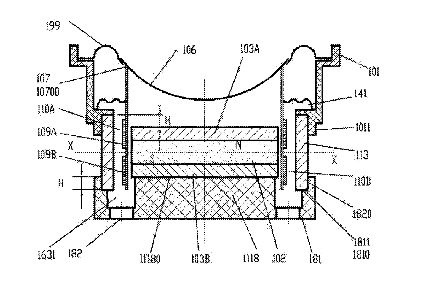
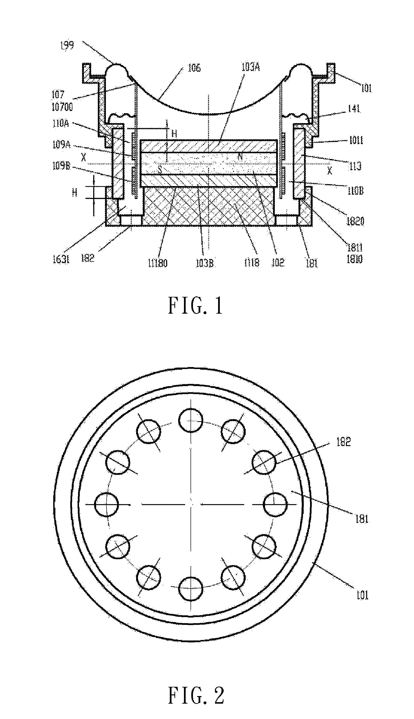
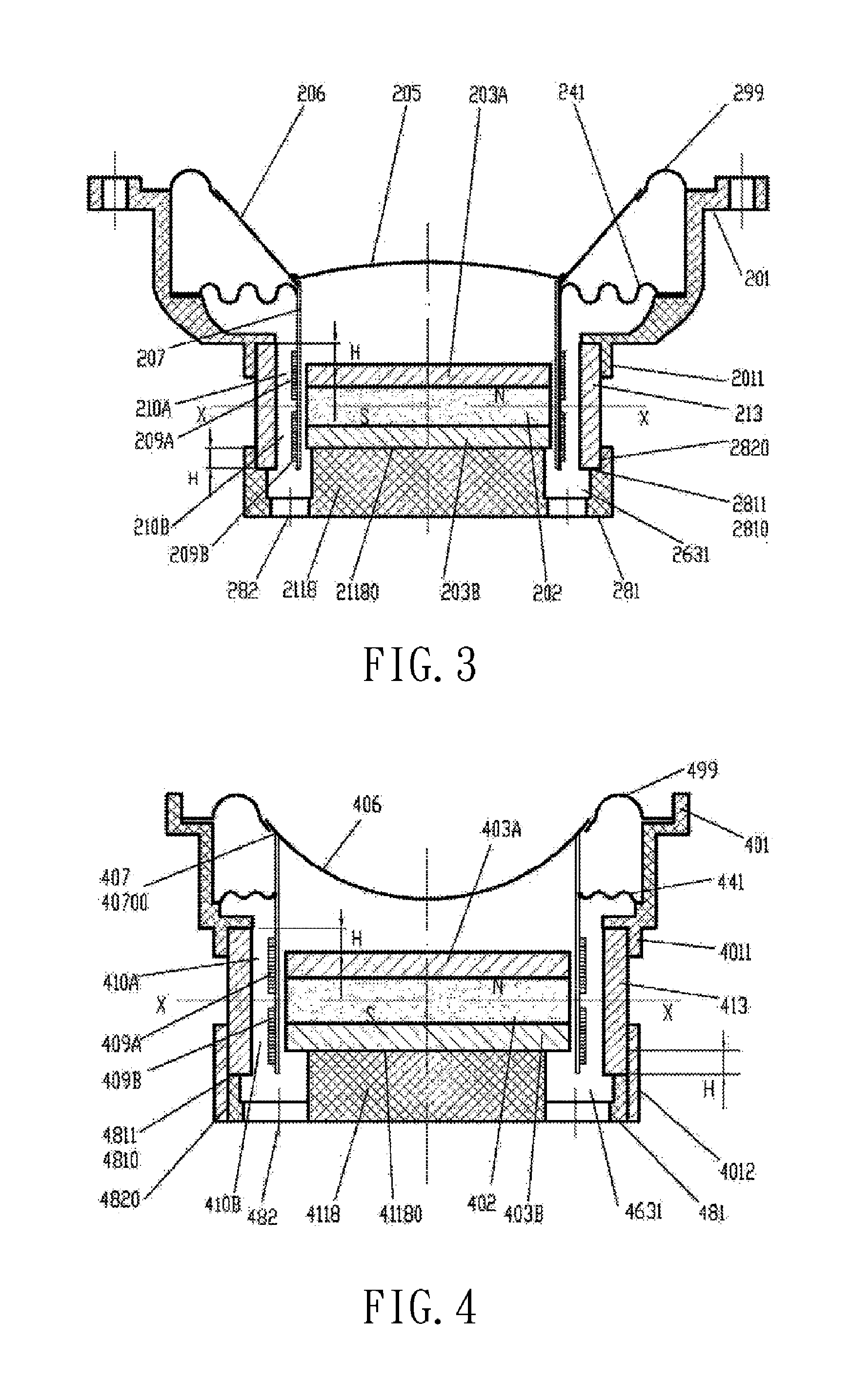
[0087]FIG. 1 shows a longitudinal section view of Embodiment 1 according to the present invention. It is an embodiment of an inner magnetic speaker with double magnetic gaps and double coils. The upper polar plate 103A and the lower polar plate 103B are two circular flat plates which have the same thickness and the same projected area and which are mounted coaxially, and a Nd—Fe—B magnet 102 is sandwiched between the elements 103A and 103B. At the axial center of a bracket 181 made of aluminium-alloy, there is arranged an inwardly convex circular platform 1118, with a smooth and well-defined vertical outer circular surface and with 0.01-0.05 mm of negative tolerance less in diameter than the elements 103A and 103B. The element 1118 is provided with an annular groove 1631 at its outerside, with twelve through holes 182 evenly disposed in the bottom of the groove. At the outerside the element 1631, there is an annular thin wall of the bracket which has smooth and well-defined inner an...

embodiment 5

[0097]FIGS. 17-A and 17-B are diagrams showing schematically a second wiring of the two groups of symmetrical coil circuits as mentioned in Embodiment 5 according to the present invention. This also an embodiment of a speaker with three magnetic gaps and three coils.

[0098]Embodiment 7 of FIG. 8 has the same frame, magnetic circuit structure and relevant describing contents as Embodiment 4, with only one difference in the wiring manner of the three coils as follows:

[0099]When the two outer coils 309A′ and 309C′ have a clockwise winding direction as viewed from the outerside direction of the vibrating membrane, the intermediate coil 308B′ must have a counter-clockwise winding direction, and vice versa. It is set to dispose a central tap YB′ at the a half number of turns of the coil 309B′ to thereby constitute two equally-divided coils 309B1′ and 309B2′. The tail YA′ of the coil 309A′ is in serial connected with the head XB1′ of the coil 309B1′, the head XC′ of the coil 309C′ is in ser...

embodiment 8

[0116]FIG. 9 is a longitudinal section view of Embodiment 8 according to the present invention. It is an embodiment of an inner magnetic speaker with four magnetic gaps and four coils. Similarly, by means of a fastener 960 of non-magnetic material, the three units of magnetized polar plates and permanent magnet are pressed together to be firmly while conveniently adhered to the inwardly convex platform of the aluminium-alloy bracket.


PUM

PropertyMeasurementUnit
Lengthaaaaaaaaaa
Lengthaaaaaaaaaa
Angleaaaaaaaaaa

Abstract

An inner magnetic transducer with multiple magnetic gaps and multiple coils, and a preparation method thereof. The inner magnetic transducer with multiple magnetic gaps and multiple coils includes a non-magnetic material frame and a non-magnetic material bearer frame. The inner magnetic transducer with multiple magnetic gaps and multiple coils includes two or more coaxial annular magnetic gaps with the same diameter value, two suits of symmetric magnetic paths, and a symmetric coil. In the transducer, enwinding direction, connection mode and parameters of coils are decided, in order to ensure that the value of the inductance of coils and the opposing electromotive force obtained during the process of moving to and fro are counteracted by each other. The inner magnetic transducer with multiple magnetic gaps and multiple coils has resistance load character or approximately has a resistance load character, simultaneously, has high sensitivity, high analytic capability, and high fidelity.

Description

BACKGROUND[0001]1. Field of the Invention[0002]The present invention, which belongs to the field of electroacoustic transducers and mechanical-electrical transducers in electricity, relates to a transducer and in particular to an inner magnetic transducer with multiple magnetic gaps and multiple coils.[0003]2. Background of the Related Art[0004]During one-hundred-thirty years since the world's first moving-coil speaker (hereinafter referred to as speaker) was granted for a patent for invention in 1877, almost all the speakers of commercial production are equipped with only one magnetic gap and one coil, except those as disclosed by the invention patents of U.S. Pat. No. 5,849,760 in the name of USA HARMAN Company, CN951010204 in the name of JAPAN ALPINE Company, and CN99114781.2, CN00122197.3, U.S. Pat. No. 6,795,564 and TW88109796 in the name of the present inventor and the like. When the coil is connected to an audio signal current, a left-handed electrodynamic force F is generate...

Claims


Application Information

Patent Timeline
IPC IPC(8): H04R9/06B32B37/12H01F13/00B32B37/14
CPCH04R9/025H04R9/063H04R9/046H04R2209/041H04R9/02
Inventor ZHANG, FAN
Owner ZHANG FAN
Learn More