
Semiconductor laser based intra-cavity optical micro-fluidic biosensor

a microfluidic biosensor and micro-fluidic technology, applied in the field of biosensors, can solve the problems of increasing operation difficulty and cost, increasing the contribution of ground mode to interfere constructively or destructively, and increasing the operation difficulty, so as to simplify the whole biosensor system, high performance, and versatile function

Inactive Publication Date: 2012-08-02
ZHEJIANG UNIV
View PDF4 Cites 11 Cited by
  • Summary
  • Abstract
  • Description
  • Claims
  • Application Information

AI Technical Summary

Benefits of technology

[0020]1. The quality factor of the output spectrum of the laser is much greater than that of passive structures, thus the sensor has much higher sensitivity.
[0021]2. The monolithically integrated solution makes the device compact, highly integrated, suitable for mass production, and consequently low cost.
[0022]3. The active / passive integration does not require an external light source which greatly reduces the operation complexity.
[0023]4. The detection of power ratio does not require the use of expensive optical spectrum analyzer which simplifies the whole bio-sensor system.
[0024]The present invention has the potential of low-cost, high performance and versatile functionality, and may find applications in medical diagnostics biological science, drug analysis, environmental monitoring and other fields.

Problems solved by technology

These widely reported sensors all need an additional external light source or a spectrometer to analyze the sensing characteristics, which greatly increased the operation difficulty and cost.
Depending on the relative phase of the surface plasmon modes, their contributions to the ground mode will interfere constructively or destructively.
However, the passive biosensor needs to introduce external light source excitation, which increases the operation difficulty.
Besides, the detection limit still has a large room for improvement.
The sensitivity of the structure is limited because the length of the cavity with microfluidic channel is very small.

Method used


Image

  • Semiconductor laser based intra-cavity optical micro-fluidic biosensor
  • Semiconductor laser based intra-cavity optical micro-fluidic biosensor
  • Semiconductor laser based intra-cavity optical micro-fluidic biosensor

Examples


Embodiment Construction

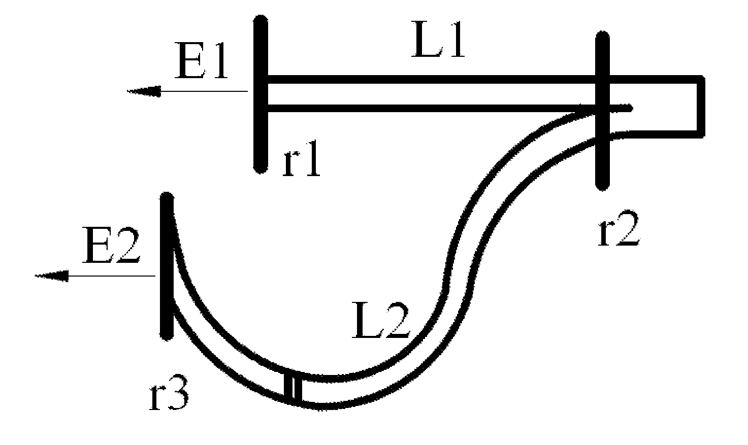
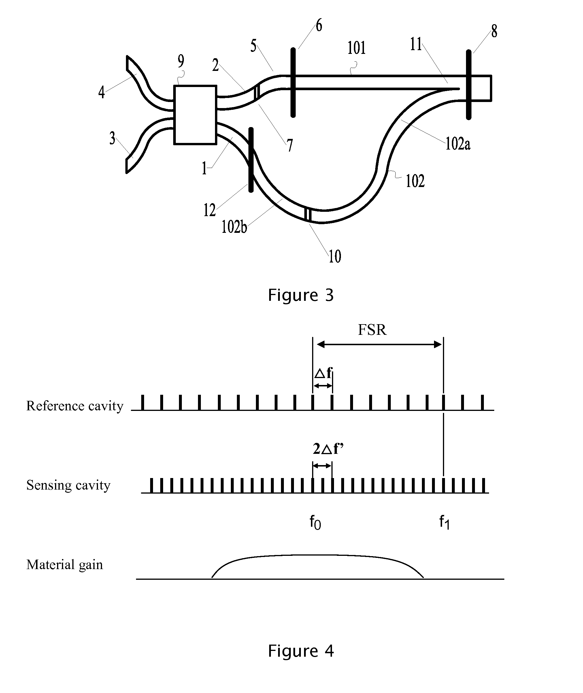
[0042]FIG. 3 is the first implementation of the present invention. The semiconductor laser based intra-cavity optical micro-fluidic biosensor comprises a reference cavity 101, a sensing cavity 102, a 2×2 coupler 9 and a phase adjustment section 5 on either input port of the 2×2 coupler. Two optical waveguide arms are placed in the reference cavity 101 and the sensing cavity 102, respectively. The two optical waveguides are very close to each other on one end (the close end), but are far away from each other on the other end (the open end). Each optical waveguide has partially reflecting mirrors on both ends, which can be a cleaved facet or rectangular deep etched trench, as indicated by elements 6, 8, 12 in FIG. 3. Each optical waveguide and the partially reflecting mirrors on both ends constitute a Fabry-Perot cavity. At least one portion of each of the waveguides in the reference cavity 101 and in the sensing cavity 102 has an electrode for injecting current to provide optical gai...


PUM


Abstract

A semiconductor laser based intra-cavity optical micro-fluidic biosensor comprises a coupled-cavity semiconductor laser, a 2×2 coupler and a phase adjustment section on one input port of the coupler. The dominant mode of the coupled-cavity laser appears in one output port of the coupler, while the adjacent mode comes out from the other output port of the coupler. The resonant frequency interval of the sensing cavity is slightly larger or smaller than one half of that of the reference cavity. Part of the sensing cavity is the sensing section which is covered by an analyte. The refractive index change of the analyte will cause the lasing mode of the coupled cavity to switch to an adjacent mode, resulting in a π-phase change in the phase difference between the two output ports of the two resonance cavities. By applying the Vernier effect, the power ratio of the two output ports of the coupler will change and the refractive index change of the analyte can be derived. A detection limit of 10−8 RIU or smaller can be achieved.

Description

FIELD OF THE INVENTION[0001]This invention relates generally to a biosensor, more particularly to an intra-cavity optical micro-fluidic biosensor based on a monolithically integrated semiconductor laser.BACKGROUND OF THE INVENTION[0002]Biochemical detection and environmental monitoring has become another important application field for integrated optoelectronic devices after the great success of optical communication. Optical biosensors have attracted considerable attention because of their immunity to electromagnetic interference, noninvasive detection, shorter response time and higher sensitivities, and in particular, because they are the only technology that allows the direct detection of biomolecular reactions. Integrated optical biosensors enable the analysis instruments to develop towards high integration density, high sensitivity and high compactness, and also make it possible for simultaneous detection of multiple parameters on a monolithic integrated biosensor array. In add...

Claims


Application Information

Patent Timeline
IPC IPC(8): G01N21/41
CPCG01N21/7746G01N2021/0346G01N2021/391G01N21/45G01N2021/458G01N21/05G01N2021/399
Inventor HE, JIAN-JUNYU, TINGTINGLOU, MIN
Owner ZHEJIANG UNIV
Learn More