Fluidized-bed reactor and hydrotreating method thereof

a technology of fluidized bed and reactor, which is applied in the field of reactors, can solve the problems of increasing the proportion of residual oil yield against crude oil, low yield and quality of liquid products, and low yield of liquid products, so as to improve the yield of light oil and prolong the residence time. , the effect of enhancing the conversion ratio

Active Publication Date: 2012-08-16
CHINA PETROCHEMICAL CORP +1
View PDF0 Cites 15 Cited by
  • Summary
  • Abstract
  • Description
  • Claims
  • Application Information

AI Technical Summary

Benefits of technology

[0042]The present invention's technique is simple, scientific and reasonable. As compared with the prior arts, the fluidized bed reactor and the hydrogenation method thereof according to the present invention present the following advantages:
[0043]1) In the fluidized bed reactor according to the method of the present invention, one or more circulation zones are provided, which may form several fluidizing operation zones, enabling the operation of the whole fluidized bed reactor more flexible.
[0044]2) The presence of circulation zones prolongs residence time of liquid component in the fluidized bed reactor, resulting in a better yield of light oil.
[0045]3) Since the fluidized bed reactor is one with a rather high back-mixing level, the effluent of the reactor generally contains part of the unreacted raw material. Through arranging a plurality of small inner circulation zones, raw material can be conversed in cycle for several times, and the conversion ratio can be enhanced.
[0046]4) The phase separator of the fluidized bed reactor is of a simple cylinder structure, which has advantages of simple manufacturing process, low production cost and easy installation and maintenance compared to the taper or cone shaped phase separator of the prior arts.
[0047]5) The technology using an expanded bed reactor and a fluidized bed reactor in combination, as compared with a single reactor, prolongs the reaction path and time, improves the impurity removal rate of the reactants, and enhances the product quality accordingly.

Problems solved by technology

Though the facility investment for decarbonization is low, the yield and quality of liquid products are low, and the decarbonization cannot satisfy the current environmental requirements.
At the same time, as there is a serious trend that the crude oil is becoming heavier and inferior in quality, the proportion of the residual oil yield against the crude oil is increasing by year, even reaching 70 wt % or above.
At the moment, the comparatively mature residual oil hydrogenation technology is hydrogenation of residual oil with fixed bed, but this technology is restricted by the nature of the raw material, and has a comparatively strict requirement on some parameters such as metal in raw material and carbon residue etc.
As in the hydrogenation method with suspended bed a rich amount of heavy metal exists in the tail oil, the processing and utilization of tail oil are very difficult.
This method has a fairly good hydrogenation effect, but requires a large amount of catalyst, and the hydrogenation activity of catalyst is not utilized sufficiently.
Nevertheless, directly adding fresh catalyst into the fluidized bed reactor may easily cause transient fluctuation of the above conditions, resulting in transient instability on fluid state and operating conditions within the reactor.
Further, since the initial activity of fresh catalyst is high, adding it directly into the fluidized bed reactor and enabling it to contact and mix with inferior heavy residual oil raw material will result in rapid carbon accumulation of catalyst and fast activity loss, which will influence hydrogenation effect of the reaction flow and increase replacement frequency of catalyst.
None of these prior arts, however, discloses the on-line treatment of catalyst when the catalyst within the reactor cannot meet the requirement on activity.
In this process, catalyst is directly added into the fluidized bed reactor by gravity, which lead to a rapid carbon accumulation when initially active catalyst contacts with inferior raw material, hence deactivation rate and replacement frequency of catalyst are both enhanced.
At the same time, as the temperature pre-heating catalyst and hydrogen is lower than the reaction temperature, the reaction temperature within the fluidized bed will be fluctuated, rendering an unstable operating condition and a low product quality.
This technology, however, has the following deficiencies in its practical use: there is a small storage amount of catalyst within the reactor, and the space utilization of the reactor is low; the maintenance of the circulation pump is costly; and once the circulation pump works abnormally or is damaged, catalyst will be sunk and aggregated so that the device has to stop running.
Further, when the liquid product in the reactor stays for too long a time under non-catalytic hydrogenation conditions, it will easily be subject to a second thermal cracking reaction to form coke under a high temperature, resulting in an inferior product quality.
Nevertheless, as the height-diameter ratio of the fluidized bed reactor is rather big, generally 1:6 to 1:8, and most of the effective reaction space is an empty tube structure except the tri-phase separator at the top of the reactor, there lacks a positive mass transfer structure, so that the mass transfer effect among gas, liquid and solid is rather poor.
Thus, the hydrogenation effect of liquid phase product is insignificant, and the product quality is poor.
Further, the fluidized bed reactor is a back-mixing reactor, i.e., part of unreacted raw material is discharged out of the reactor together with reacted flow, hence the conversion rate of raw material is rather low.
Although with the advantage that heat energy can be reasonably utilized, it still has the following disadvantages: the reactor is huge, causing difficulties in transportation, installation, operation and maintenance; with the increase of reaction sections in one reactor, the number of tri-phase separators also increases, hence the structure of the whole reactor is complicated; also, the more tri-phase separators, the more space they will occupy in the reactor, and the smaller effective reaction space for gas, liquid and solid there will be left, which means the resources will be wasted since the fluidized bed reactor operated under high temperature and high pressure is very costly; further, for the operation under multiple sections connected in series, it requires a stable operating condition and a very good design of gas-liquid distribution plate between sections, and when there are transient fluctuations, the separating effect of the tri-phase separator will be influenced, such that the solid entrained with the gas and liquid will block the distribution plate and influence the normal stable operation of the device.

Method used


Image

  • Fluidized-bed reactor and hydrotreating method thereof
  • Fluidized-bed reactor and hydrotreating method thereof
  • Fluidized-bed reactor and hydrotreating method thereof

Examples


example 2

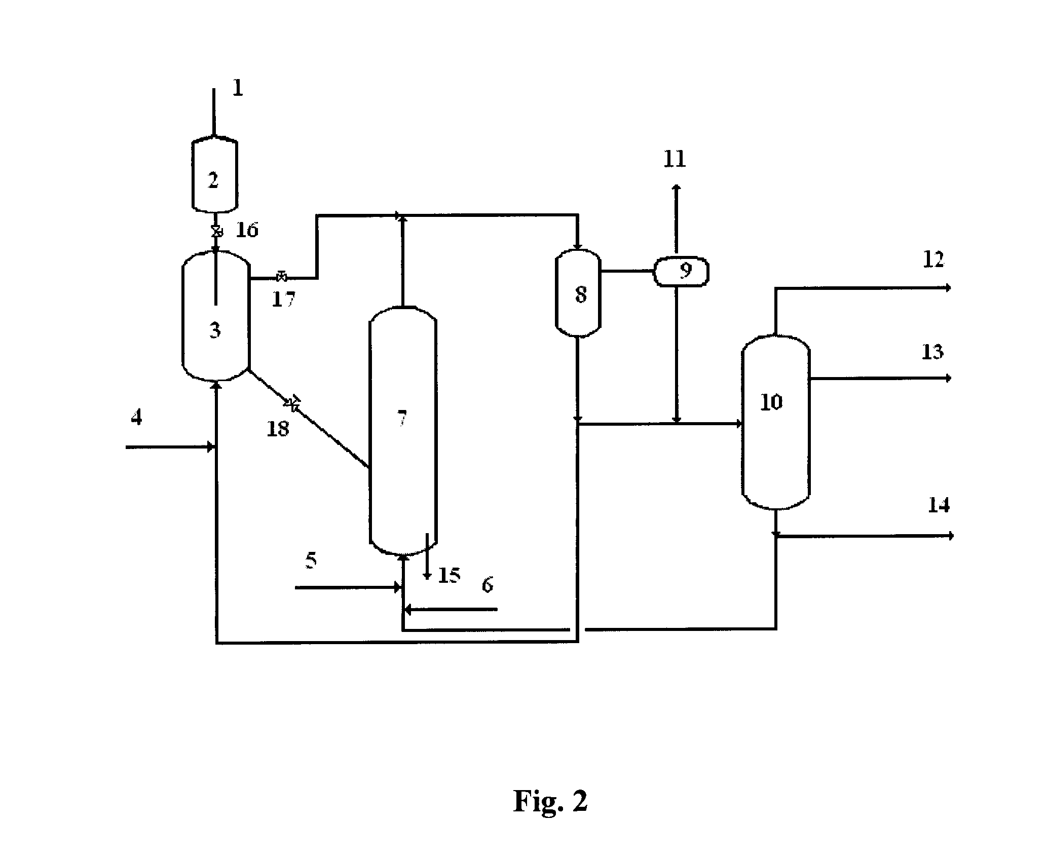
[0068]This Example relates to a hydrogenation method with the fluidized bed reactor according to the present invention. The operation process is as shown in FIG. 2, and there is one inner circulation zone arranged in the fluidized bed reactor.

[0069]The process is as follows. Heavy hydrocarbon-containing raw material 6, after being blended with hydrogen 5, enters into the fluidized bed reactor 7 in an upflow manner and is contacted and reacted with the catalyst. After hydrogenated in the fluidized bed, the flow is discharged from the top of the reactor and enters into the high pressure separating device 8 for gas-liquid separation. The liquid-phase resultant amounting to 15 wt % of the reacted liquid-phase flow is blended with hydrogen 4, and upflows into the expanded bed reactor 3 for further hydrogenation reaction. The reacted resultant is discharged from the upper part of the reactor into the high pressure separating device 8. The gas flow separated from the high pressure separati...

example 3

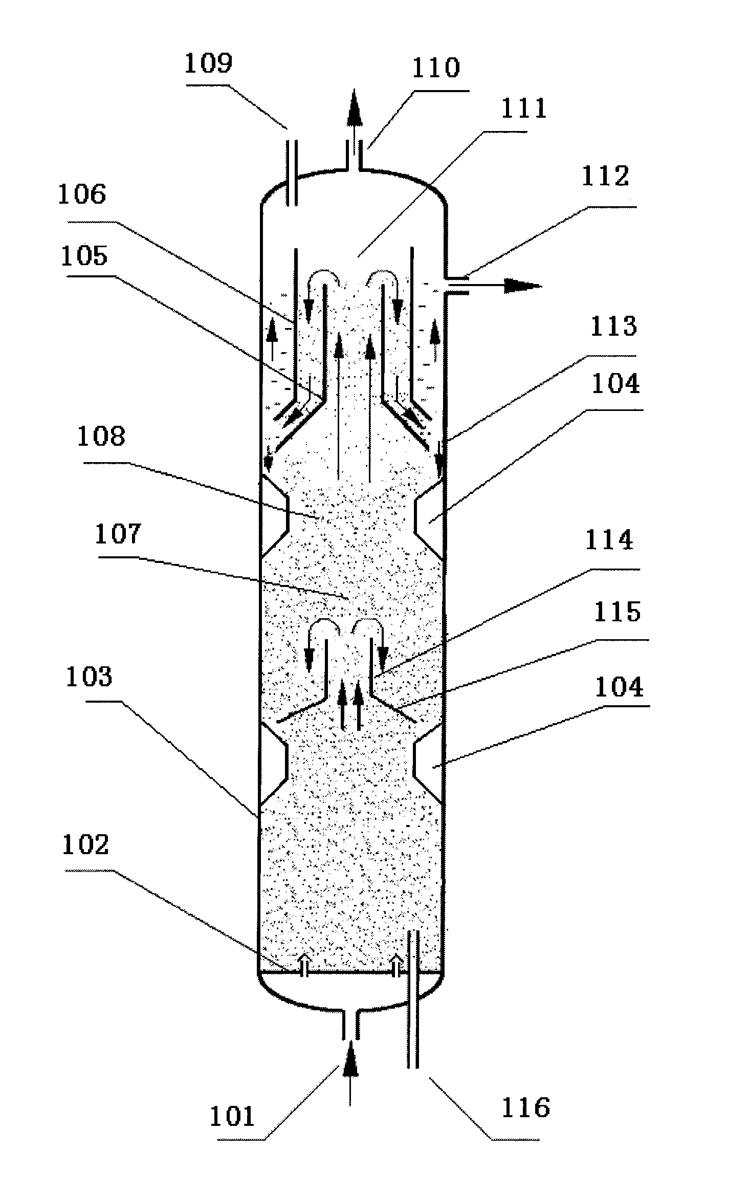
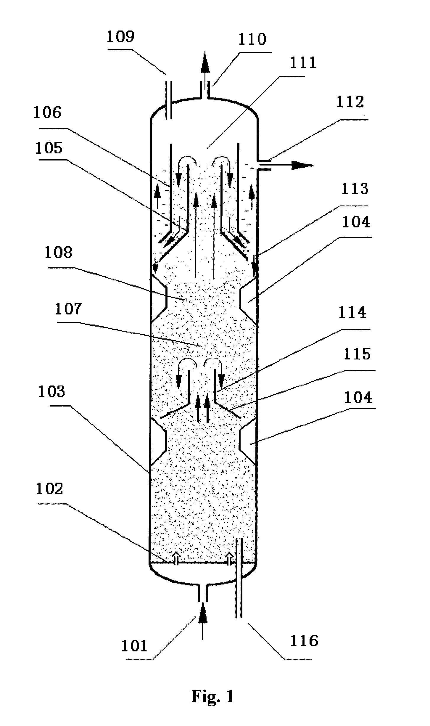
[0071]The process of Example 3 is the same as that of Example 2, and the basic structure of the fluidized bed reactor is the same as that of Example 1, except that there are two circulation zones in the fluidized bed reactor of Example 3.


PUM

PropertyMeasurementUnit
friction angleaaaaaaaaaa
cone vertex angleaaaaaaaaaa
temperatureaaaaaaaaaa

Abstract

The invention relates to a fluidized bed reactor and a hydrogenation method thereof. The fluidized bed reactor (7) comprises a reactor shell (103) vertical to the ground and a phase separator (111) at the upper part of the shell (103). An inner circulation zone is provided under the phase separator (111), and comprises a cylinder (114), a tapered diffusion section (115) and a guiding structure (104). In the hydrogenation method using the fluidized bed reactor (7), an expanded bed reactor (3) is used to further hydrogenate part of the product from the fluidized bed reactor (7), and supply catalyst without influencing on the stable operation of the fluidized bed reactor (7).

Description

TECHNICAL FIELD [0001]The present invention relates to a reactor and a process using the reactor, and more specifically, to a fluidized bed reactor and a hydrogenation method thereof.BACKGROUND ART[0002]Following developments of heavy crude oil and changes of the demand structure for petroleum products around the world, the market shows a rapidly increasing demand for light fuel oil and fast decreasing demand for heavy fuel oil. Heavy oil processing technology has become a crucial R&D subject for oil-refining industry. The heavy oil processing technology mainly comprises decarbonization and hydrogenation.[0003]Decarbonization mainly comprises solvent deasphalting, coking and heavy oil catalytic cracking, etc. Though the facility investment for decarbonization is low, the yield and quality of liquid products are low, and the decarbonization cannot satisfy the current environmental requirements. At the same time, as there is a serious trend that the crude oil is becoming heavier and i...

Claims


Application Information

Patent Timeline
Patent Type & Authority Applications(United States)
IPC IPC(8): C10G45/00B01J8/24
CPCB01J8/007C10G2300/1077B01J21/04B01J23/85B01J23/883B01J35/023B01J35/1042B01J35/1061B01J35/108B01J2208/0084C10G1/06C10G45/08C10G45/20C10G65/04C10G2300/4018C10G2300/1033C10G2300/107B01J8/226B01J8/1854B01J8/1872C10G45/56C10G47/30C10G49/16
Inventor JIA, LIJIA, YONGZHONGGE, HAILONG
Owner CHINA PETROCHEMICAL CORP
Why Eureka
Try Eureka