Optical module

a technology of optical modules and optical insulators, applied in the field of optical modules, can solve problems such as damage to ld light source units, and achieve the effects of high isolation properties, high extinction ratio, and high extinction ratio

Active Publication Date: 2012-09-20
SHIN ETSU CHEM IND CO LTD
View PDF8 Cites 5 Cited by
  • Summary
  • Abstract
  • Description
  • Claims
  • Application Information

AI Technical Summary

Benefits of technology

[0013]It is an object of the present invention to provide a small-size and high extinction ratio optical device. In particular, it is to provide a small-size Faraday optical device having a high extinction ratio that is suitable as an optical isolator having high isolation properties used in a high output laser used for laser machining, optical measurement, optical communication, etc., for example a fiber laser.
[0014]It is another object of the present invention to provide an optical module that combines the use of a Faraday rotator having a high Faraday effect and a high extinction ratio with a magnet having a small external form. Other objects of the present invention will become apparent from the explanation below.

Problems solved by technology

However, although a fiber laser is characterized by a narrow light emission spectrum and excellent conversion efficiency, it is very sensitive to returning light due to reflected light, its properties become unstable if reflected light returns from an end face bonded to the optical fiber or from a metal surface having high reflectance and, consequently, this causes the possibility that the LD light source unit might be damaged due to high output light emission.

Method used


Image

  • Optical module
  • Optical module
  • Optical module

Examples


example 1

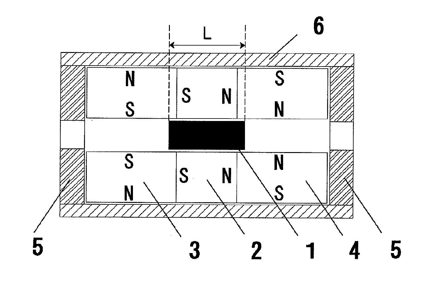
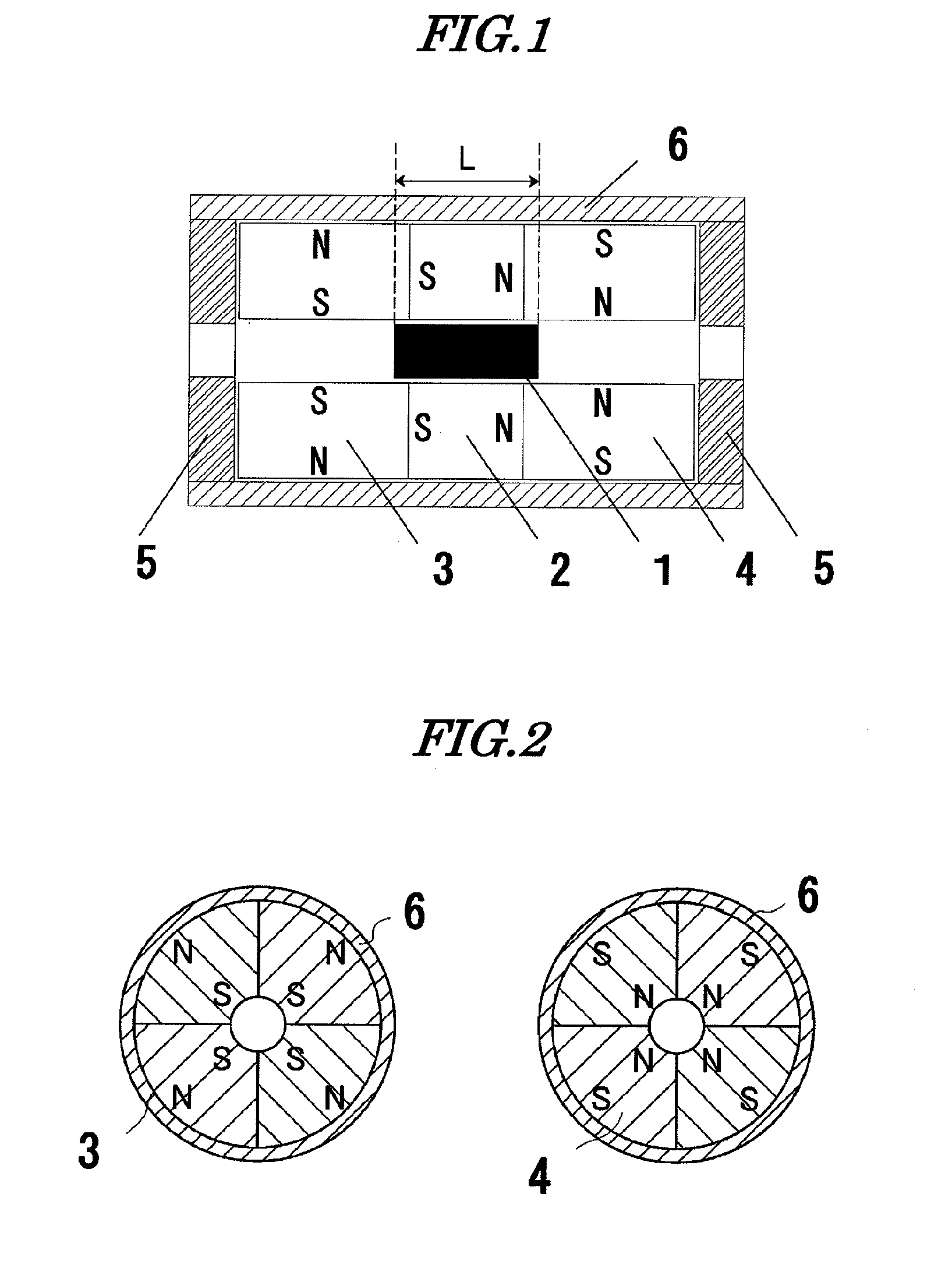
[0121]An optical module having the constitution shown in FIG. 1 was prepared.

[0122]As the Faraday rotator, a terbium yttrium oxide having a Verdet constant of at least 0.27 min / (Oe·cm) at a wavelength of 1.06 μm was used as a sample length of 0.7 to 1.1 cm. A hollow magnet comprising a neodymium-iron-boron (NdFeB) system magnet was disposed on the outer periphery of the Faraday rotator. A magnetic circuit was formed by disposing hollow magnet units that were equally divided into four in directions of 90 degrees relative to the optical axis and having opposite magnetic field polarities on opposite sides of the hollow magnet, the magnetic field polarity of the respective divided magnets being in a direction normal to the optical axis. A carbon steel housing was disposed on the outside of the magnet and the magnet units.

[0123]The Faraday rotator 1 used in Example 1 is now explained in detail. The material was a ceramic containing terbium yttrium oxide at 99.99 wt %, the composition the...

examples 2 and 3

[0124]The relationship between the Tb content ratio x (0.5 to 1.0) in Formula (1) above and the Verdet constant was examined. Example 2 was carried out in the same manner as in Example 1 except that a ceramic containing an oxide having a composition of (Tb0.5Y0.5)2O3 for which x=0.5 at the same wt % was used.

[0125]Furthermore, Example 3 was carried out in the same manner as in Example 1 except that a ceramic containing a Tb2O3 oxide for which x=1.0 at the same wt % was used.

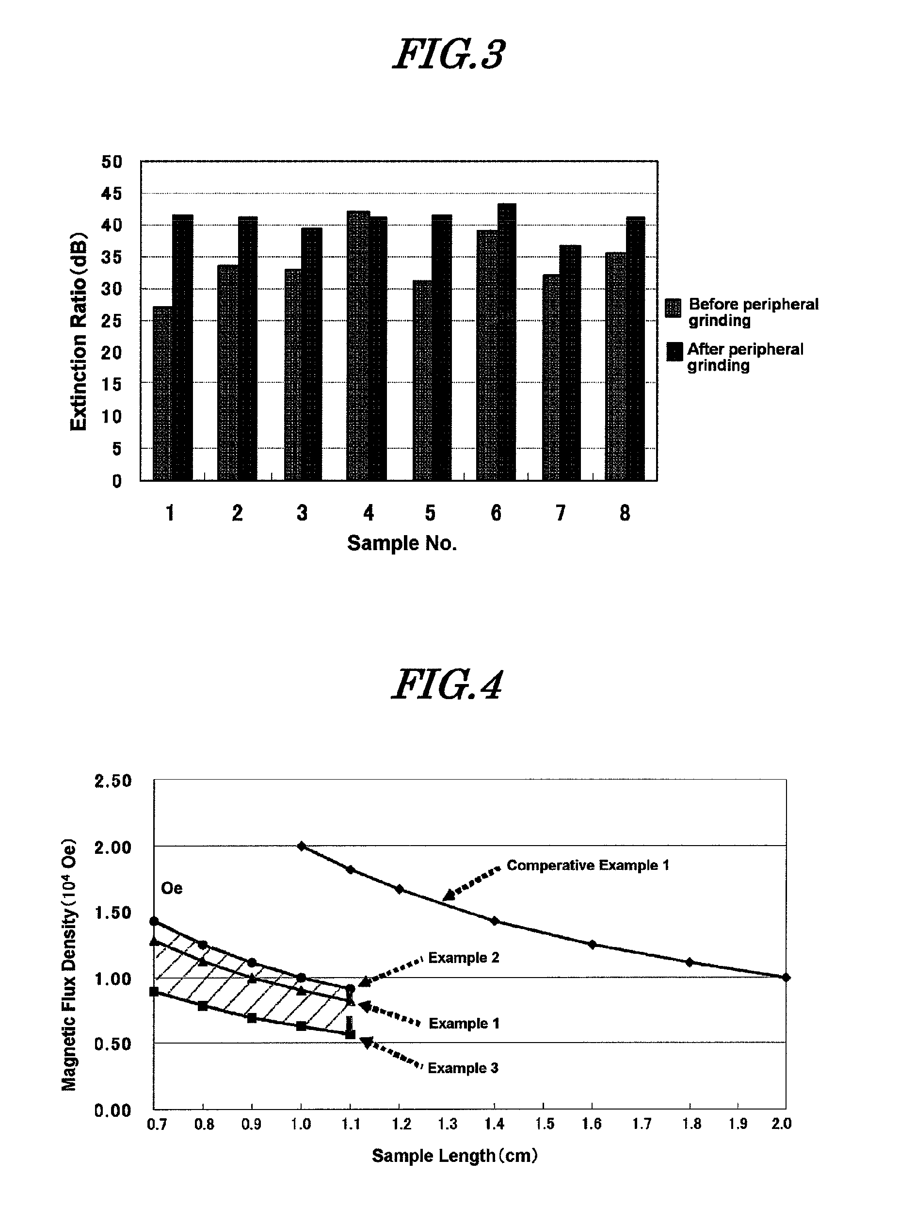
[0126]The Verdet constant of the ceramics having these compositions was measured. From the results, it was found that the Verdet constant was 0.27 min / (Oe·cm) for x=0.5, and 0.43 min / (Oe·cm) for x=1.0. Furthermore, the extinction ratio was 43 dB in both Examples 2 and 3.

[0127]FIG. 4 shows the magnetic flux density T (104 Oe) that gave a Faraday rotation angle of 45 degrees as a function of sample length L (cm) when the sample length of the ceramic used in Examples 1 to 3 was changed from 0.7 to 1.1 cm in 0.1 cm i...


PUM

PropertyMeasurementUnit
insertion lossaaaaaaaaaa
wavelengthaaaaaaaaaa

Abstract

An optical module is provided that includes a Faraday rotator having a Verdet constant at a wavelength of 1.06 μm of at least 0.27 min/(Oe·cm), a first hollow magnet disposed on the outer periphery of the Faraday rotator, and second and third hollow magnet units disposed so as to sandwich the first hollow magnet on the optical axis. The second and third hollow magnet units include 2 or more magnets equally divided in a direction of 90 degrees relative to the optical axis. A magnetic flux density B (Oe) applied to the Faraday rotator is in the range of 0.5×10⁴≦B≦1.5×10⁴. The Faraday rotator is disposed on a sample length L (cm) in the range of 0.70≦L≦1.10, and has an external diameter D (cm) in the range of 0.20≦D≦0.60.

Description

BACKGROUND OF THE INVENTION[0001]1. Technical Field[0002]The present invention relates to an optical module comprising a Faraday rotator, which is an essential component of an optical isolator that is used in a wavelength region of about 1 μm.[0003]2. Background Art[0004]Conventionally, industrial laser machines that are used in applications such as cutting, welding, or marking employ a CO2 laser (wavelength 10.6 μm) or a lamp pumped YAG laser (wavelength 1 μm).[0005]In recent years, the requirements for machining performance have become more strict, and there has been a desire for a laser machine having higher precision, higher output, and longer life. Among such market requirements, attention is being focused on fiber lasers. A fiber laser is characterized by all optical paths being formed from optical fiber and by being capable of fiber-outputting laser light having high precision and high output by amplifying 1-μm-band light emitted from a laser diode (LD) light source using fib...

Claims


Application Information

Patent Timeline
Patent Type & Authority Applications(United States)
IPC IPC(8): G02F1/09B24B1/00
CPCG02F1/093C30B11/00C30B29/24C30B15/08C30B13/00H01F7/0273
Inventor YAHAGI, AKIRAWATANABE, TOSHIAKI
Owner SHIN ETSU CHEM IND CO LTD
Why Eureka
Try Eureka