Methods and apparatus for detecting airborne molecular contaminants

a technology of airborne molecular contaminants and methods, applied in the direction of mass spectrometers, instruments, separation processes, etc., can solve the problems of difficult to use almost any analytical technique to investigate the composition of contaminated substances and thus trace their origin, lack of knowledge of what contaminants will form deposits, and sophisticated and expensive analytical techniques. to achieve the effect of improving sensitivity

Active Publication Date: 2012-09-27
TSI INC
View PDF6 Cites 17 Cited by
  • Summary
  • Abstract
  • Description
  • Claims
  • Application Information

AI Technical Summary

Benefits of technology

[0011]Still other embodiments of the invention operate on the phenomenon of radiolytic particle formation as a way to both selectively detect and to remove AMCs that are capable of forming particles. Hereinafter, AMCs that are capable of forming particles are referred to as “harmful AMCs.” In one embodiment, particles that are formed radiolytically are captured and optionally re-gasified for analysis. The flow stream is conditioned by the condensing of the particles radiolytically, which removes the harmful AMCs from the flow stream. The re-gasification can selectively increase the concentration of the contaminants that are capable of forming ultraviolet haze films for enhanced analytical sensitivity.
[0012]Compared with the current methods, the various embodiments of the invention are more practical than current methods and apparatuses for identifying contaminants because they identify only species that are of interest. There is no response to gases that are non-particle-forming. Inactive species do not interfere with the measurement and method. Various embodiments of the present invention are substantially lower in cost than existing methods and apparatuses for contaminant detection and removal.
[0014]Radiolytic formation of particles has been regarded mainly as a nuisance in aerosol science, due to the non-discriminate production of particles of unknown composition that interfere with the particles to be measured. Certain embodiments of the invention utilize these characteristics of radiolytic particle production to provide the advantage of sensing when AMCs may form harmful particles having harmful consequences such as ultraviolet haze.
[0015]Structurally, various embodiments of the invention utilize a substantially monochromatic light source such as an actinic-wavelength laser light that emerges from an optical fiber, or is focused on a clean substrate. The high density actinic-wavelength light at the surface of the fiber or substrate can cause the formation of deposits on the surface of the fiber or substrate when in the presence of AMCs. Such phenomena can sometimes be observed with the transmission of laser light through single-mode optical fibers, causing a so-called “polymer bump” to grow on the end of the fiber. The deposits disturb the laser beam wavefront. The distortion of the emerging wavefront ultimately leads to a change in the beam intensity profile from a smooth Gaussian shape to one with rings and other irregularities. Prior to these gross effects, far more subtle changes in the wavefronts can be detected, for example by interferometry. Hence, enhanced sensitivity may be provided by using an interferometer to detect wave-front shape changes or phase changes.
[0017]In other embodiments of the invention, radiolytic formation of particles condenses the contaminant material in the form of nanometer-scale particles, which are then accumulated by filtration. The accumulated material is not only removed from the flow stream (thus conditioning the flow stream) but can then be released into a small gas or liquid volume, thus effecting a high degree of concentration and increasing the sensitivity of any analytical technique used to investigate the contaminant material and origin. By allowing the contaminant to form particles under ionizing radiation, and capturing these particles on a filter, only materials that are problematic are accumulated, regardless of their composition.

Problems solved by technology

Certain gaseous contaminants cause problems due to deposition or formation of particles or haze matter on sensitive surfaces involved in a photolithography process during processing.
While the detailed processes leading to particle formation is the subject of ongoing research, it is clear that they originate from gases because they cannot be eliminated by particle filtering.
The contaminant concentration can be so low, e.g. parts per trillion, that it becomes difficult to use almost any analytical technique to investigate the contaminant composition and thus trace its origin.
Existing work in the area of particle contamination produced by AMCs uses sophisticated and expensive analytical methods such as gas chromatography (GC), TOF-SIMS, and other methods to identify gaseous chemical species present regardless of whether these species cause particle deposition.
These methods suffer from lack of knowledge of what contaminants will form the deposits.
Ultimately this could lead to understanding the chemical reactions and pathways leading to particle deposition, but it is a long and difficult process.
This method correctly targets even unknown contaminants capable of forming the haze, but suffers from insufficient sensitivity due to mass detection limits.
Aside from detection of AMCs, removal of harmful AMCs also poses significant challenges.
Gas filters and absorbers can be utilized in principle, but it is very difficult to reach the parts-per-trillion purity levels needed to prevent haze formation.
Therefore, elimination of AMCs that cause haze poses a significant problem.
Another technique is to distill the AMCs out of the air, which is a costly process.

Method used


Image

  • Methods and apparatus for detecting airborne molecular contaminants
  • Methods and apparatus for detecting airborne molecular contaminants
  • Methods and apparatus for detecting airborne molecular contaminants

Examples


Embodiment Construction

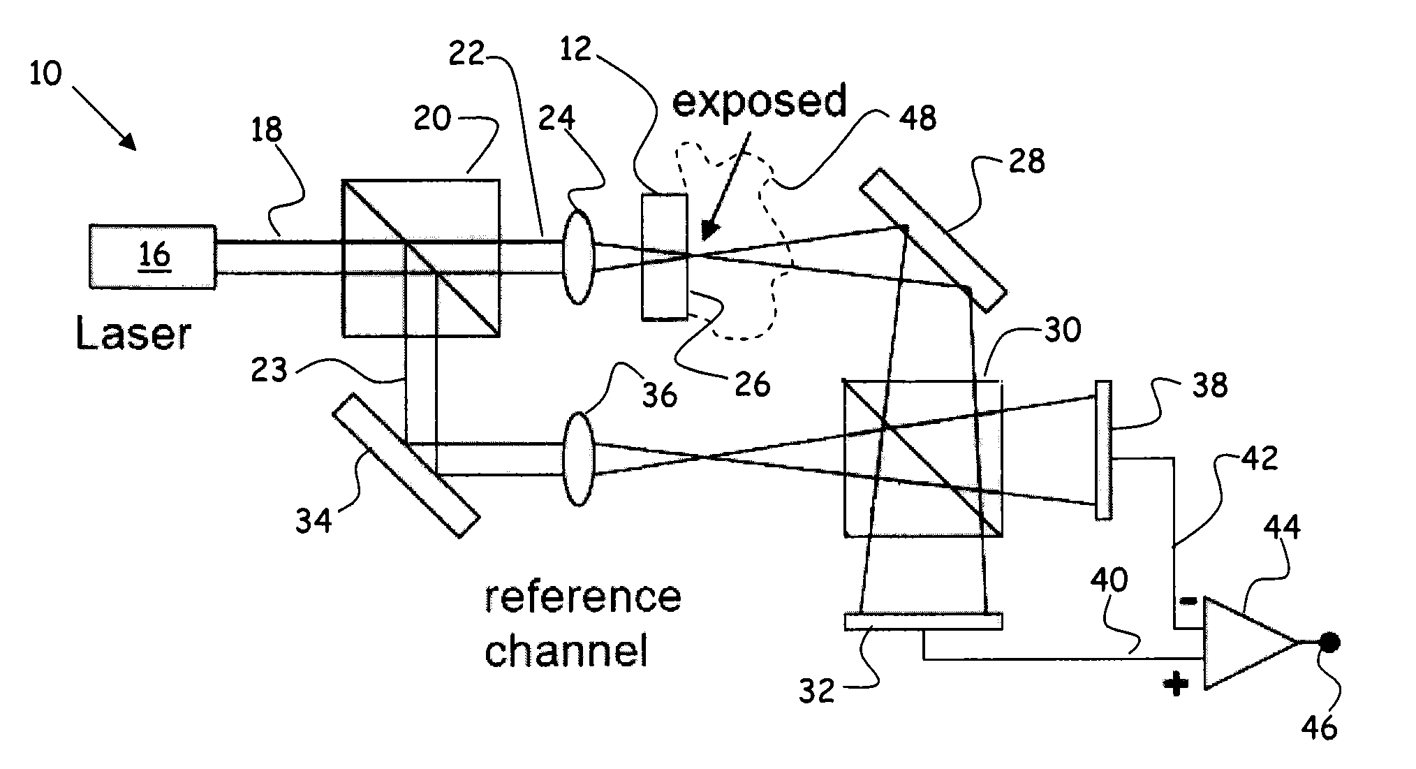
[0044]Referring to FIG. 1, a Mach-Zender type interferometric system 10 including a substrate element 12 for gathering deposits from airborne molecular contaminants (AMCs) is depicted in an embodiment of the invention. The interferometric system 10 includes an electromagnetic source 16 (in this case a laser) that propagates a primary beam 18 of electromagnetic radiation at a substantially monochromatic wavelength. In this embodiment, the primary beam 18 is routed through a beam splitter 20 that splits the primary beam 18 into a test beam 22 and a reference beam 23. The test beam 22 is routed through a set of optical components comprising a focusing optic 24 and the substrate element 12, the focusing optic 24 focusing the test beam 22 at a measuring surface 26 of the substrate element 12. The test beam 22 can be routed via a redirecting optic 28 through a second beam splitter 30 before being subtended by a test beam detector 32.

[0045]Likewise, the reference beam 23 can be routed thro...


PUM

PropertyMeasurementUnit
diameteraaaaaaaaaa
diameteraaaaaaaaaa
optical path lengthaaaaaaaaaa

Abstract

Methods and apparatuses for the removal, analysis and / or detection of harmful airborne molecular contaminants (AMCs). In one embodiment, an ionizing radiation source is utilized to remove the harmful AMCs from a flow stream via radiolytic particle generation and subsequent capture by filtration. The captured particles may be released, for example, by re-gasification for analysis at much higher concentrations. In another embodiment, the ionizing radiation source is utilized with a particle detector to sense when harmful AMCs are present. In one embodiment, a solid optical medium is exposed to a monitored environment so that the AMCs are in contact with a surface of the solid optical medium. A focused light beam is arranged to emerge from a solid optical medium at an energy density sufficient to cause the AMCs to form deposits on the exposed surface of the solid optical medium, which can be detected using an interferometric technique.

Description

RELATED APPLICATIONS[0001]This application claims the benefit of U.S. Provisional Application No. 61 / 393,962, filed Oct. 18, 2010, and of U.S. Provisional Application No. 61 / 393,965, filed Oct. 18, 2010, the disclosures of which are hereby incorporated by reference in their entirety.BACKGROUND[0002]“Airborne molecular contaminants” or AMCs, is a term of art in the area of clean room operation, referring to gaseous contaminants. Certain gaseous contaminants cause problems due to deposition or formation of particles or haze matter on sensitive surfaces involved in a photolithography process during processing. Such surfaces include semiconductor wafers, lenses, mirrors, beam splitters, photomasks, semiconductor wafers, and pellicle films. While the detailed processes leading to particle formation is the subject of ongoing research, it is clear that they originate from gases because they cannot be eliminated by particle filtering.[0003]A consequence of AMCs is the formation of “ultravio...

Claims


Application Information

Patent Timeline
Patent Type & Authority Applications(United States)
IPC IPC(8): G01N21/59G01B9/02H01J49/26B03C3/155
CPCG01N21/45G01N21/94G01N15/065G01N15/0612G01N2021/458
Inventor KAUFMAN, STANLEY L.
Owner TSI INC
Why Eureka
Try Eureka