Method for producing electrostatic chuck and electrostatic chuck

Active Publication Date: 2012-10-04
NGK INSULATORS LTD
View PDF9 Cites 6 Cited by
  • Summary
  • Abstract
  • Description
  • Claims
  • Application Information

AI Technical Summary

Benefits of technology

[0017]In the first method for producing electrostatic chucks according to the present invention, in step (a), a third ceramic molded body may be prepared as with the first and second ceramic molded bodies; in step (b), a third ceramic calcined body may be prepared as with the first and second ceramic calcined bodies; in step (c), a heater electrode paste may be printed on a surface of one of the second and third ceramic calcined bodies to form a heater electrode; and in step (d), the first and second ceramic calcined bodies may be superposed on each other so as to sandwich the electrostatic electrode, the second and third ceramic calcined bodies may be superposed on each other so as to sandwich the heater electrode, and the first to third calcined bodies in such a state may be subjected to hot-press firing to prepare a ceramic sintered body. In this manner, the variation in thickness of the dielectric layer of an electrostatic chuck having built-in electrostatic electrode and heater electrode can be suppressed to a low level.
[0018]In the second method for producing electrostatic chucks according to the present invention, in step (a), a third ceramic molded body may be prepared as with the first and second ceramic molded bodies; in step (b), a heater electrode paste may be printed on a surface of one of the second and third ceramic molded bodies to form a heater electrode; in step (c), the third ceramic molded body may be dried, debound, and calcined as with the first and second ceramic molded bodies to prepare a third ceramic calcined body; and in step (d), the first and second ceramic calcined bodies may be superposed on each other so as to sandwich the electrostatic electrode, the second and third ceramic calcined bodies may be superposed on each other so as to sandwich the heater electrode, and the first to third calcined bodies in such a state may be subjected to hot-press firing to prepare a ceramic sintered body. In this manner, the variation in thickness of the dielectric layer of an electrostatic chuck having built-in electrostatic electrode and heater electrode can be suppressed to a low level.
[0019]In the first and second methods for producing electrostatic chucks, in step (a), a mixture of alumina and MgF2 serving as a sintering aid may be used as the ceramic powder, and, in step (d), the hot-press firing temperature may be set within a range of 1120° C. to 1300° C. When no sintering aid is added, the hot-pres

Problems solved by technology

However, according to the methods of Patent Literatures 1 and 2, since the methods each include a firing step after pressure-molding the alumina powder placed on the electrostatic electrode, the electrostatic electrode inside the multilayered fired body undergoes significant warpage due to co-firing of the sintered body and the molded body and due to variation in density of the alumina powder in the molded body.
If the

Method used


Image

  • Method for producing electrostatic chuck and electrostatic chuck
  • Method for producing electrostatic chuck and electrostatic chuck
  • Method for producing electrostatic chuck and electrostatic chuck

Examples


Example

[0046]Examples embodying the present invention will now be described. In Examples 1 and 2, alumina was used as a ceramic material. In Example 1, an electrostatic chuck was prepared as shown in FIG. 2A and in Example 2, an electrostatic chuck was prepared as shown in FIG. 2(b). In Examples 3 and 4, aluminum nitride was used as a ceramic material. In Example 3, an electrostatic chuck was prepared as shown in FIG. 2A, and in Example 4, an electrostatic chuck was prepared as shown in FIG. 2B. In Comparative Examples 1 and 2, alumina was used as a ceramic material. In Comparative Example 1, an electrostatic chuck was prepared by a method similar to that shown in FIG. 2A and in Comparative Example 2, an electrostatic chuck was prepared by a method similar to that shown in FIG. 2B.

Example 1

1. Preparation of Ceramic Molded Bodies

[0047]A hundred parts by weight of an alumina powder (average particle diameter: 0.50 μm, purity:. 99.7%), 0.04 parts by weight of magnesia, 3 parts by weight of a ...

Example

Example 2

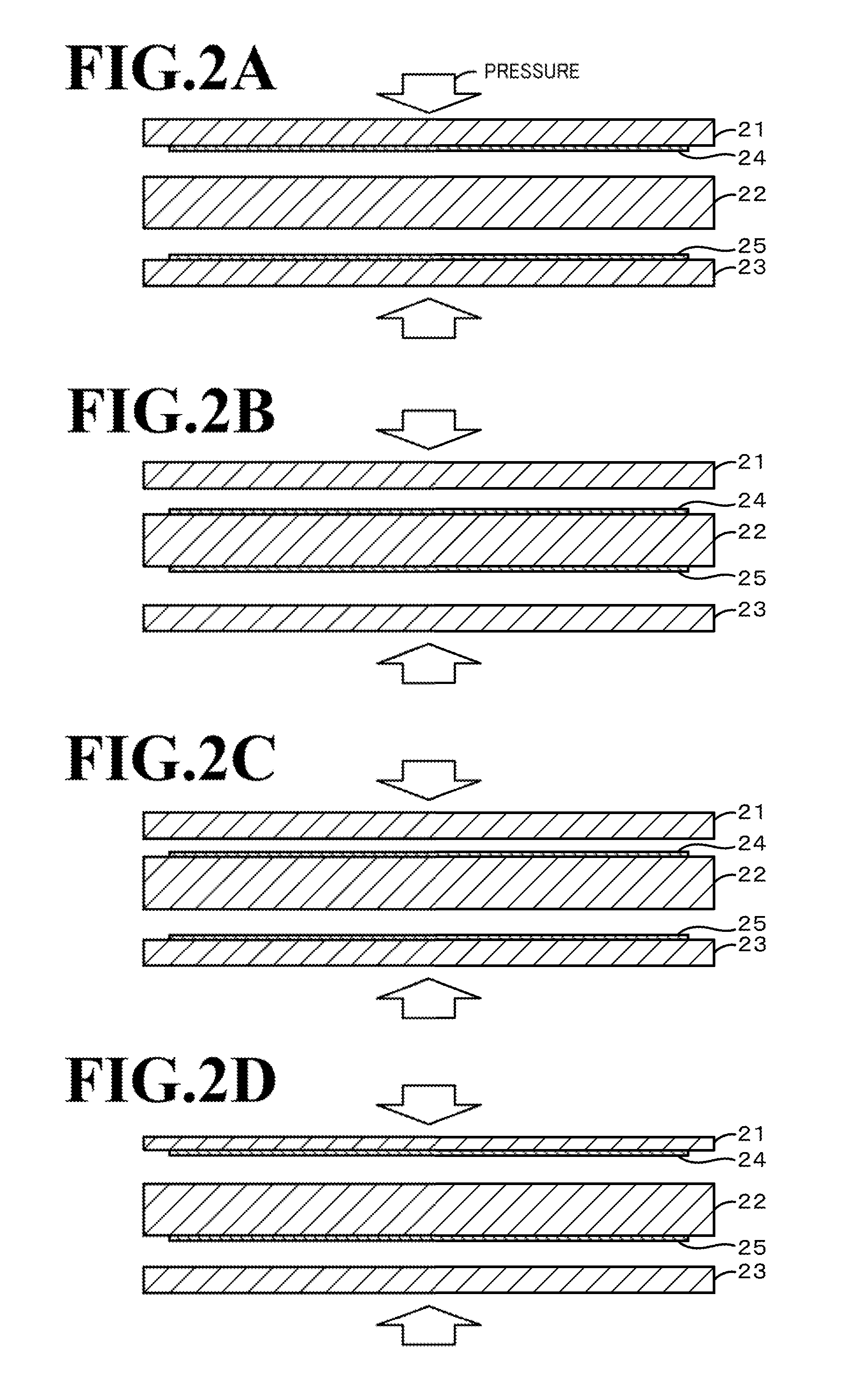
[0051]In section 3. of Example 1, screen-printing was not conducted on the first and third ceramic calcined bodies but the electrode paste was screen-printed on one surface of the second ceramic calcined body to form an electrostatic electrode and on the other surface of the second ceramic calcined body to form a heater electrode. In section 4. of Example 1, as shown in FIG. 2B, the first to third ceramic calcined bodies were superposed and subjected to hot-press firing to form a sintered body. Subsequently, side processing and hole drilling were conducted and terminals were attached to obtain an electrostatic chuck having built-in electrostatic electrode and heater electrode. The conditions for the hot-press firing were the same as those in Example 1. The resulting electrostatic chuck had a carbon content of 0.1 wt % or less and a relative density of 98% or more. The variation in the thickness of the dielectric layer was 55 μm.

Example

Example 3

1. Preparation of Ceramic Molded Bodies

[0052]A hundred parts by weight of an aluminum nitride powder (average particle diameter: 0.5 μm, purity: 99.7%), 3 parts by weight of europium oxide, 8.7 parts by weight of alumina, 0.4 parts by weight of titanium oxide, 3 parts by weight of a polycarboxylic acid copolymer serving as a dispersing agent, and 25 parts by weight of a polybasic acid ester serving as a solvent were weighed and mixed in a ball mill (trommel) for 14 hours to prepare a slurry precursor. To the slurry precursor, 7.7 parts by weight of 4,4′-diphenylmethane diisocyanate as an isocyanate, 1.4 parts by weight of ethylene glycol as a polyol, and 0.3 parts by weight of 6-dimethylamino-1-hexanol as a catalyst, each serving as a gelling agent, were added, and the resulting mixture was stirred for 10 minutes by using a blade stirrer to obtain a ceramic slurry. The ceramic slurry was poured into a first molding die having a disk-shaped inner space 350 mm in diameter a...


PUM

PropertyMeasurementUnit
Grain sizeaaaaaaaaaa
Temperatureaaaaaaaaaa

Abstract

A method for producing an electrostatic chuck includes the steps of (a) placing a ceramic slurry in a molding die, the ceramic slurry containing a ceramic powder, a solvent, a dispersing agent, and a gelling agent, gelatinizing the ceramic slurry in the molding die, and removing the molding die to obtain first and second ceramic molded bodies; (b) drying, debinding, and calcining the first and second molded bodies to obtain first and second ceramic calcined bodies; (c) printing an electrostatic electrode paste on a surface of one of the first and second ceramic calcined bodies to form an electrostatic electrode while assuming the first ceramic calcined body is to form a dielectric layer of an electrostatic chuck; and (d) superposing the first and second ceramic calcined bodies on each other to sandwich the electrostatic electrode and subjecting the first and second calcined bodies to hot-press firing.

Description

BACKGROUND OF THE INVENTION[0001]1. Field of the Invention[0002]The present invention relates to a method for producing an electrostatic chuck and an electrostatic chuck.[0003]2. Description of Related Art[0004]Methods, for producing electrostatic chucks known heretofore include methods for producing double-layered electrostatic chucks and methods for producing triple-layered electrostatic chucks.[0005]A known example of the former is a method that includes a step of forming an alumina sintered body, a step of printing an electrode paste for forming an electrostatic electrode on the alumina sintered body, a step of placing alumina powder on the electrode paste to conduct die-molding, and a step of firing a molded body integrated in the step of die-molding (refer to Patent Literature 1). Patent Literature 1 also discloses that an alumina calcined body is used instead of the alumina sintered body.[0006]A known example of the latter is a method that includes a step of printing an elect...

Claims


Application Information

Patent Timeline
IPC IPC(8): B23B31/28B28B3/00
CPCB32B18/00Y10T279/23C04B35/581C04B35/6264C04B35/63456C04B35/63488C04B35/645C04B2235/3206C04B2235/3217C04B2235/3222C04B2235/3224C04B2235/3232C04B2235/445C04B2235/5445C04B2235/6023C04B2235/661C04B2235/784C04B2235/785C04B2235/786C04B2235/80C04B2235/85C04B2237/343C04B2237/366H01L21/6833C04B2235/9638C04B35/111
Inventor NOBORI, KAZUHIROEGUCHI, MASAHITOKIMURA, TAKUJI
Owner NGK INSULATORS LTD
Why Eureka
Try Eureka