Stabilization of pulsed mode seed lasers

Inactive Publication Date: 2012-10-04
ELECTRO SCI IND INC
View PDF5 Cites 6 Cited by
  • Summary
  • Abstract
  • Description
  • Claims
  • Application Information

AI Technical Summary

Benefits of technology

[0015]A programmable tailored laser pulse generator generates seed laser output in response to an electrical signal of programmable pulse shape to produce tailored laser pulses of a prescribed shape with pulse widths on the order of sub-nanosecond to hundreds of nanoseconds and fast rise times on the order of a few nanoseconds to sub-nanosecond. A first preferred tailored laser pulse generator embodiment includes a pulsed laser source in the form of a pulsed seed laser that has as its input an electrical signal to produce pulsed seed laser output. A second preferred tailored laser pulse generator embodiment includes a modulator that is positioned external to and receives output emissions from a continuous-wave seed laser to produce pulsed seed laser output. The tailored laser pulse generator produces a series of high power tailored laser pulses that are shaped in response to the electrical signal applied to the pulsed seed laser (first embodiment) or the external modulator

Problems solved by technology

Use of a traditional Gaussian-shaped laser pulse having a 5-20 ns pulse width and a sloped, gradually rising front edge in link processing tends to cause an “over crater” in the passivation layer, especially if its thickness is too large or is uneven.
Difficulty in maintaining wafer-level process control of the passivation layer during IC fabrication may result in non-optimal thickness and poor cross-wafer or wafer-to-wafer thickness uniformity.
A MOPA configuration provides a stable signal source, pulse shape, and laser beam quality but is limited by a lower laser power output level.
However, higher-power (i.e., two-watts or greater) MOPA link-processing systems in the green or ultraviolet spectrum carry a high risk of damage to the fibe

Method used


Image

  • Stabilization of pulsed mode seed lasers
  • Stabilization of pulsed mode seed lasers
  • Stabilization of pulsed mode seed lasers

Examples


Embodiment Construction

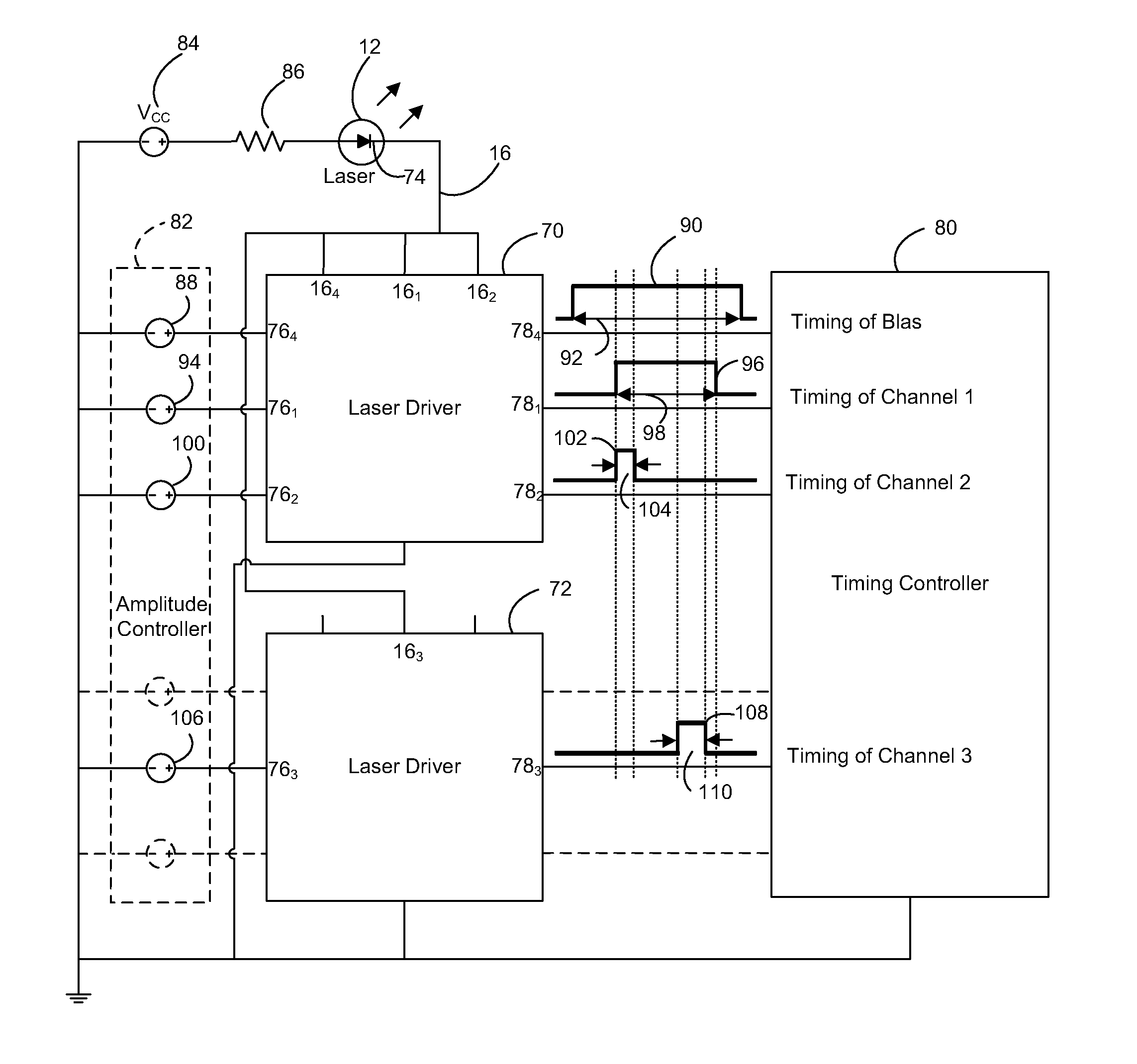
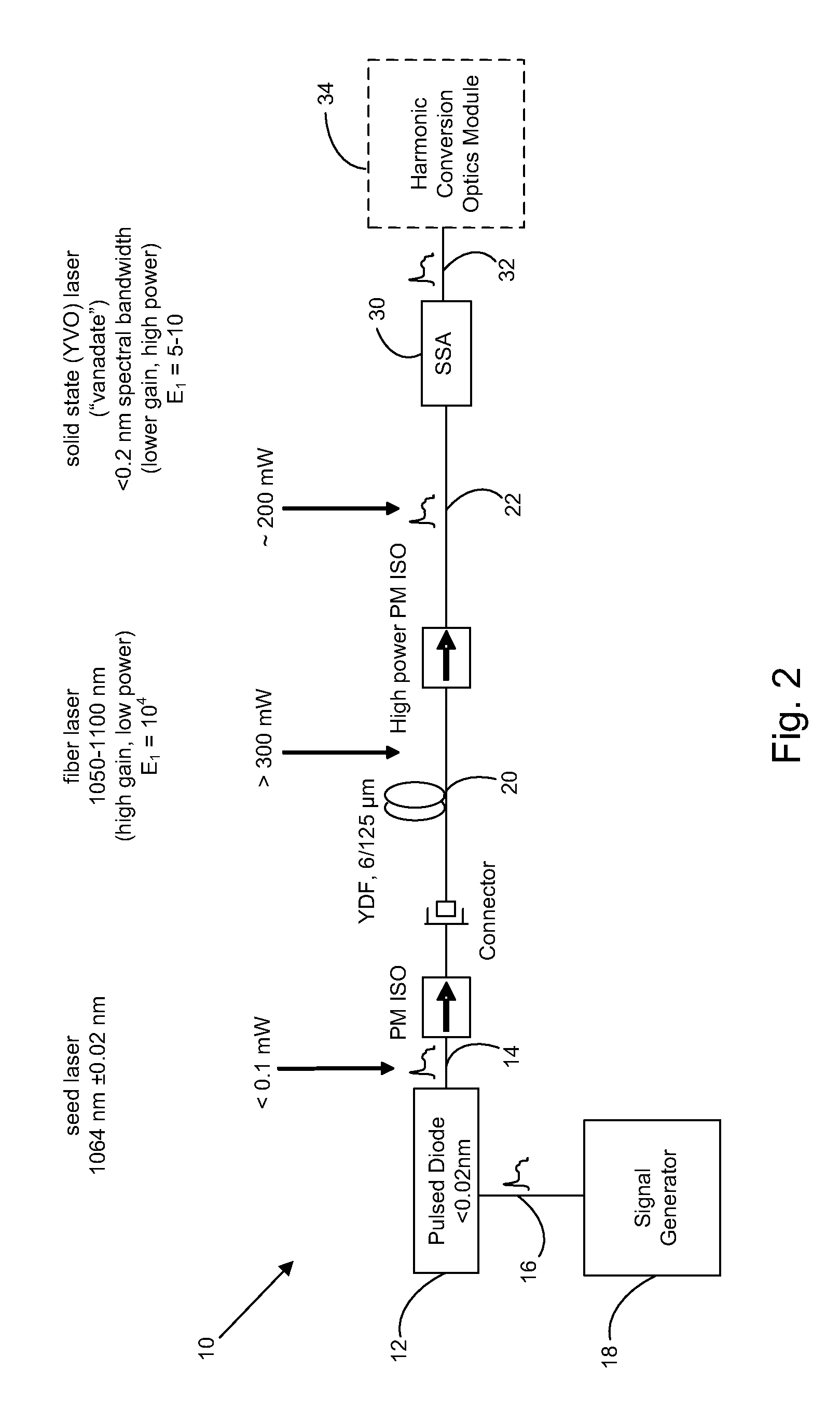
[0024]With reference to FIG. 2, in a first preferred embodiment, a programmable tailored laser pulse generator 10 includes a pulse-pumped seed diode laser 12 to produce pulsed seed laser output 14 having a laser pulse intensity profile developed in response to a tailored drive current pulse input signal 16 synthesized by a multiple channel analog signal generator 18. The spectral line width and spectral line stability of pulsed seed laser output 14 are important factors for laser processing applications, such as memory chip link severing, but are also important characteristics for developing stable amplification by solid-state laser amplifiers. Seed diode laser 12 having a stable spectral line and narrow spectral line width provides a focused laser spot size that is sufficiently small to meet laser processing needs. An example of a preferred seed diode laser 12 is a 1064 nm Single Mode Spectrum Stabilized Laser Model No. 11064SB0120P, available from Innovative Photonic Solutions, In...


PUM

PropertyMeasurementUnit
Wavelengthaaaaaaaaaa
Stabilityaaaaaaaaaa
Threshold limitaaaaaaaaaa

Abstract

A programmable tailored laser pulse generator including a pulsed seed laser source, a laser amplifier, and an optical power amplifier produces high power tailored laser pulses shaped in response to a programmable analog tailored pulse signal applied to a seed laser (first embodiment) or an external modulator of continuous-wave seed laser output (second embodiment). The programmable analog tailored pulse signal is generated by combining multiple individually programmable analog pulses generated by a multi-channel signal generator. A bias applied to the pulsed seed laser source generates pre-lasing prior to producing a tailored laser pulse so that the seed laser source spectral line and line width stabilize within a narrow gain line width of a solid-state laser amplifier, thereby to impart pulse peak stability of the laser output. The tailored laser pulse generator allows for generating harmonics at shorter wavelengths and provides an economical, reliable laser source for a variety of micromachining applications.

Description

COPYRIGHT NOTICE[0001]© 2011 Electro Scientific Industries, Inc. A portion of the disclosure of this patent document contains material that is subject to copyright protection. The copyright owner has no objection to the facsimile reproduction by anyone of the patent document or the patent disclosure, as it appears in the Patent and Trademark Office patent file or records, but otherwise reserves all copyright rights whatsoever. 37 CFR §1.71(d).TECHNICAL FIELD[0002]The present disclosure relates to generating tailored laser pulses for use in laser micromachining applications and, in particular, to methods and systems employing a highly efficient programmable tailored laser pulse generator that emits tailored laser pulses developed by a seed laser in response to programmable electrical signal pulses and amplified by a fiber laser and solid-state power amplifier.BACKGROUND INFORMATION[0003]Memory chip redundant link processing is one example of a laser micromachining application. After ...

Claims


Application Information

Patent Timeline
IPC IPC(8): H01S3/10
CPCB23K26/0084B23K26/063B23K26/385H01S3/06754H01S3/10015H01S3/1618H01S3/0092H01S3/2316H01S3/2375H01S5/0428H01S5/06216H01S3/0064H01S3/0085H01S3/1673B23K26/0622B23K26/389B23K26/355H01S5/0622H01S5/0654H01S3/10H01S3/13H01S5/068
Inventor LU, FUYUANCHANG, FENGWU, HAISHENGSUN, YUNLONG
Owner ELECTRO SCI IND INC
Why Eureka
Try Eureka