
Energy storage and generation systems

a technology of energy storage and generation system, applied in the direction of cell components, sustainable manufacturing/processing, final product manufacturing, etc., can solve the problems of limited capacity (total energy), limited power density and response time of flow batteries, and high cost or inefficiency of current electrochemical storage and generation technology, etc., to achieve fast response time, low cost, and acceptable life and performance

Inactive Publication Date: 2012-11-29
RAMOT AT TEL AVIV UNIV LTD
View PDF5 Cites 17 Cited by
  • Summary
  • Abstract
  • Description
  • Claims
  • Application Information

AI Technical Summary

Benefits of technology

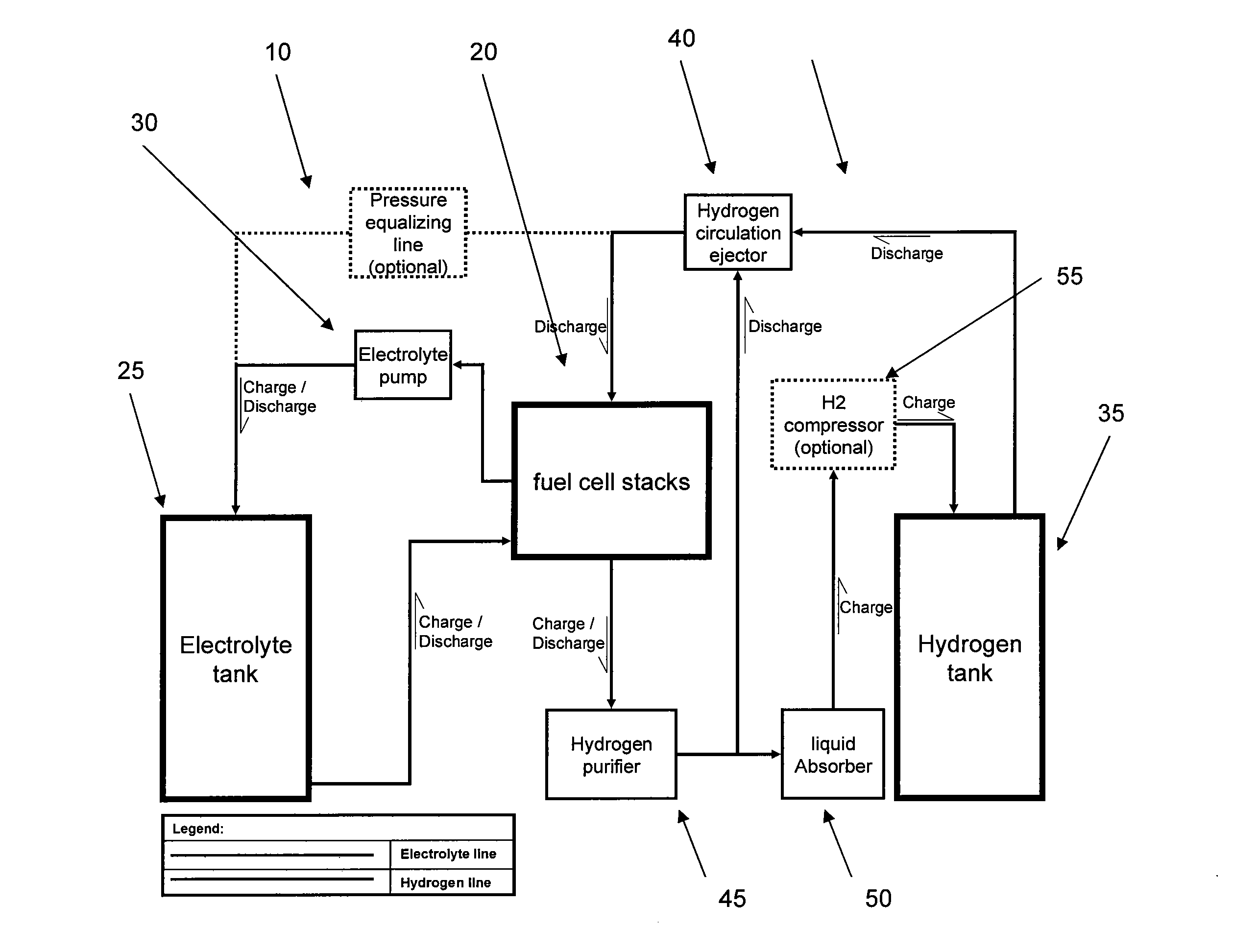
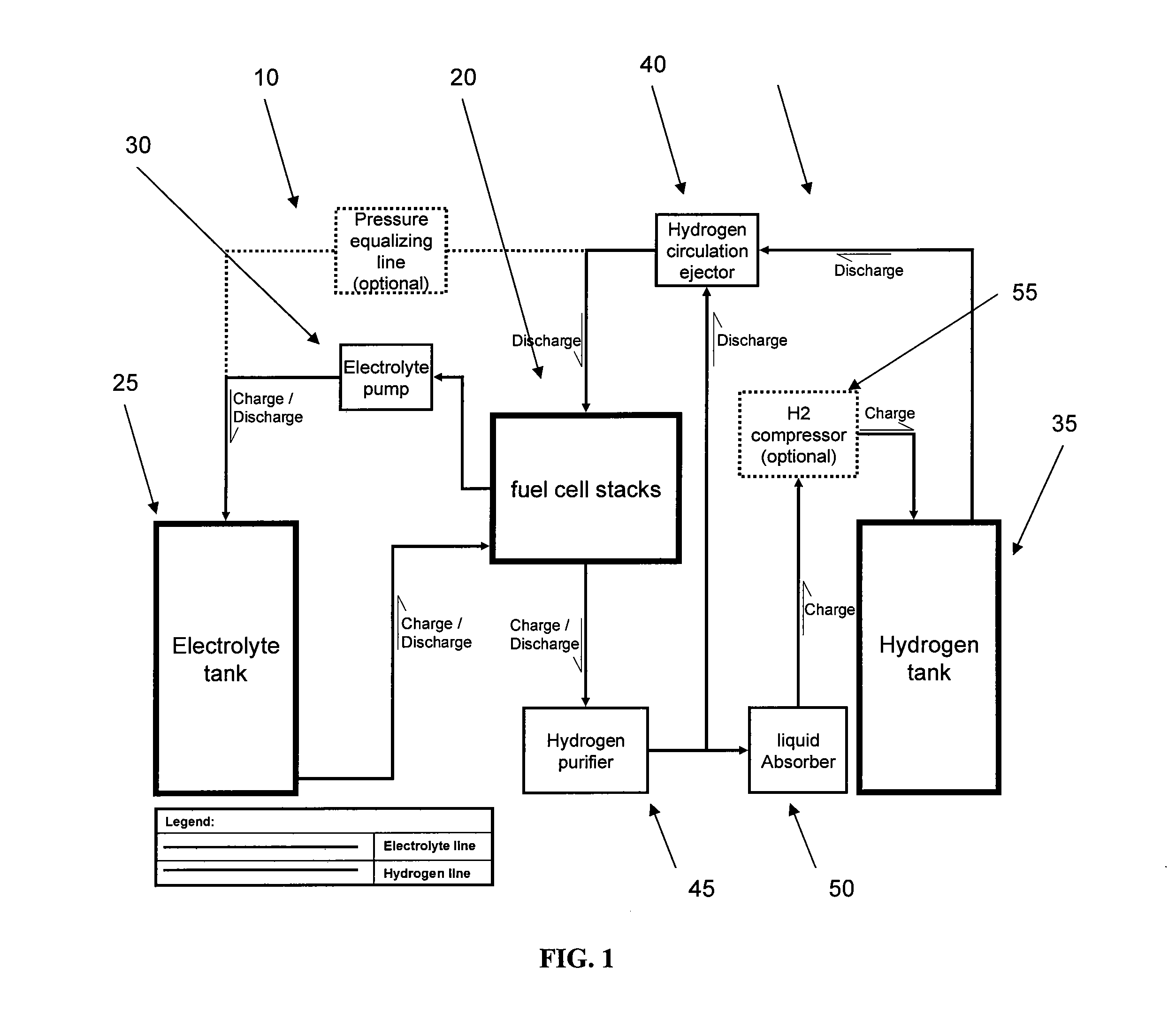
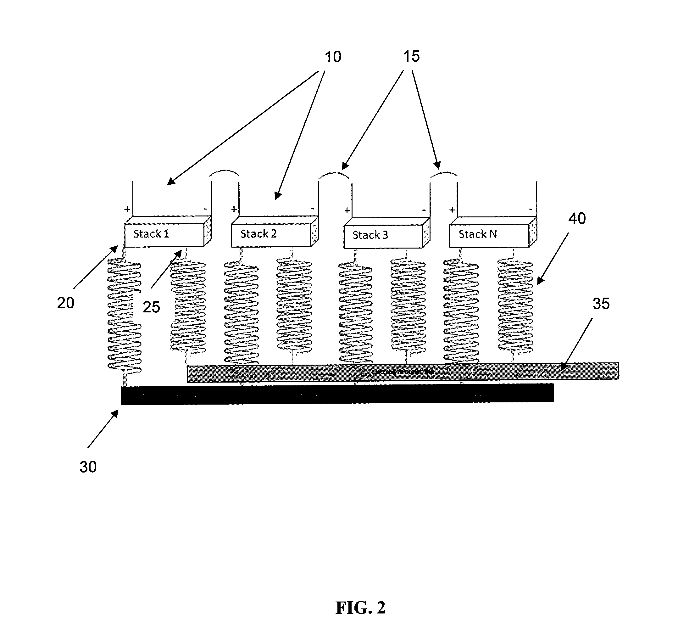
[0011]This disclosure generally relates to energy storage and generation systems, e.g., combination of flow battery and hydrogen fuel cell, that exhibit operational stability in harsh environments, e.g., both charging and discharging reactions in a regenerative fuel cell in the presence of a halogen ion or a mixture of halogen ions. This disclosure also relates to energy storage and generation systems that are capable of conducting both hydrogen evolution reactions (HERs) and hydrogen oxidation reactions (HORs) in the same system. This disclosure further relates to energy storage and generation systems having low cost, fast response time, and acceptable life and performance.

Problems solved by technology

The current technology of electrochemical storage and generation is either expensive or inefficient or both.
Generally, batteries can store and supply power at high efficiency, but are limited in capacity (total energy).
Also, flow batteries are limited in power density and response time.
Regenerative fuel cells typically operate in harsh environments that can have an adverse effect on catalyst activity in the fuel cell.
An important issue connected to catalyst activity in regenerative fuel cells that utilize, for example, a halogen acid electrolyte, is poisoning of the hydrogen catalyst by the halides.
The membrane cannot completely prevent electrolyte crossover from one side of the cell to the other.
Despite the fact that hydrogen oxidation / evolution reaction is fast and its overpotential is rather low compared to other voltage losses in the regenerative cell, in halogen ion-containing solutions, the catalyst is severely poisoned, and this raises the overpotential of the hydrogen electrode in the regenerative fuel cell.
For regenerative fuel cell such as hydrogen / bromine fuel cells, an important factor limiting its cycle life and efficiency is the degradation of the operating fuel cell materials.
These materials are exposed to a highly corrosive bromine electrolyte for long periods of time at elevated temperature.

Method used


Image

  • Energy storage and generation systems
  • Energy storage and generation systems
  • Energy storage and generation systems

Examples


example 1

Preparation of Hydrophobic Silica Beads Coated with Reactive Catalyst for Corrosive Vapor Elimination

[0147]30 grams of ⅛″ diameter silica beads with low surface area of 0.11 m2 / g were placed in oven for 1 hour at 100° C. for moisture removal. The resulting product was placed in a beaker. A 16.5 ml volumetric 1:1 solution of 60 wt % polytetrafluoroethylene (PTFE) and water was mixed until it was fully homogenized. The resulting solution was used to soak the dry silica by the incipient wetness method. The product was them placed in oven for liquid removal and PTFE curing for 15 minutes at 350° C. The final PTFE weight addition was measured to be 19%. The hydrophobic silica beads were then incipient wetted with a catalyst ink prepared from known ratios of isopropyl alcohol, tetra butyl ammonium hydroxide, per-fluoro ionic polymer and oxidation catalyst. The catalyst weight percent was calculated to be 0.5% of the total silica weight. The finished product was cured in oven for 1 hour at...

example 2

Reaction Between Bromine (Br2) and Excess Hydrogen (H2) at the Outlet of the Fuel Cell Stack

[0148]The reaction is depicted as follows: H2+Br2=2HBR ΔHf=−36.29 kJ / mol. This reaction takes place in the presence of a catalyst embedded on the surface of supporting beads. The HBr formed in the exothermic reaction is removed from the reactor by the remaining hydrogen stream in form of droplets or vapors.

example 3

Removal of Bromine from Hydrogen Rich Bromine Vapor

[0149]Referring to FIG. 5, dry hydrogen supplied from cylinder 10 was passed through flow meter 15, and into a bromine vapor rich tube device 20 having a temperature that varied from ambient to 45° C. The hydrogen rich bromine vapor then passed into another glass tube 25, with known amount of catalyst supported on hydrophobic silica beads. The reacted hydrogen was then bubbled in a water cylinder 30. The residence time of the gas passing through the catalyst was 1 second. The bromine content in the gas stream before entering the reaction tube was 10,000 ppmwt. The outlet stream bromine content was also tested and measured to be below 4 ppmwt (4 ppmwt is the measuring device lower limit). The experiment lasted for 3 months. During the experiment, total bromine weight of more than 2 times was treated by the catalyst. This is an indication that the bromine was not adsorbed but rather reacted on the catalyst.


PUM

PropertyMeasurementUnit
sizeaaaaaaaaaa
proton conductingaaaaaaaaaa
acid absorption capacityaaaaaaaaaa

Abstract

This disclosure relates to energy storage and generation systems, e.g., combination of flow battery and hydrogen fuel cell, that exhibit operational stability in harsh environments, e.g., both charging and discharging reactions in a regenerative fuel cell in the presence of a halogen ion or a mixture of halogen ions. This disclosure also relates to energy storage and generation systems that are capable of conducting both hydrogen evolution reactions (HERs) and hydrogen oxidation reactions (HORs) in the same system. This disclosure further relates to energy storage and generation systems having low cost, fast response time, and acceptable life and performance.

Description

BACKGROUND[0001]1. Field of the Disclosure[0002]This disclosure relates to energy storage and generation systems, e.g., combination of flow battery and hydrogen fuel cell, that exhibit operational stability in harsh environments, e.g., both charging and discharging reactions in a regenerative fuel cell in the presence of a halogen ion or a mixture of halogen ions. This disclosure also relates to energy storage and generation systems that are capable of conducting both hydrogen evolution reactions (HERS) and hydrogen oxidation reactions (HORs) in the same system. This disclosure further relates to energy storage and generation systems having low cost, fast response time, and acceptable life and performance[0003]2. Discussion of the Background Art[0004]There are several technologies for energy storage and generation. These technologies can be divided into three subgroups: mechanical including pumped hydro, compressed air, fly wheels, and the like; electrical including super capacitors...

Claims


Application Information

Patent Timeline
Patent Type & Authority Applications(United States)
IPC IPC(8): H02J4/00H01M8/04H01M8/18H01M8/06B82Y30/00C25B9/19
CPCH01M4/9083H01M4/921H01M4/926H01M4/96H01M8/0202Y02E60/50H01M8/0258H01M8/0271H01M8/186Y02E10/50Y02P70/50H01M4/90H01M8/02H01M8/04H01M8/24H01M8/1051
Inventor PELED, EMANUELBLUM, ARNONAHARON, ADITRAVITSKY, NINAKONRA, YARONTSAMIR, IDOZEL, VLADIMIRSAADI, KOBBYALON, MEITALGORENSHTEIN, ROY
Owner RAMOT AT TEL AVIV UNIV LTD
Learn More