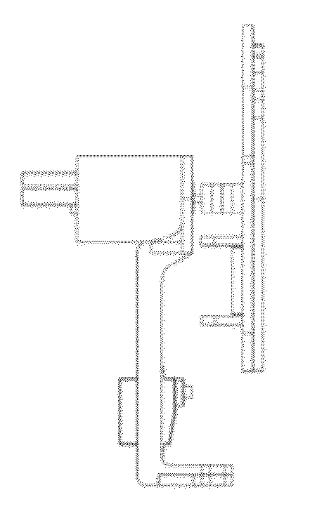
Systems and methods for sample use maximization

a sample and maximization technology, applied in the field of system and method for maximization of sample, can solve the problems of high cost of manufacturing the components of the device, inability to manufacture a poc device, and inability to perform parallel assays, and achieve the effect of high accuracy

Inactive Publication Date: 2012-12-06
THERANOS
View PDF4 Cites 266 Cited by
  • Summary
  • Abstract
  • Description
  • Claims
  • Application Information

AI Technical Summary

Benefits of technology

[0015]In one aspect, the devices and methods disclosed herein are designed to identify the sample type (blood versus plasma and etc.) to measure the volume of sample early enough in the assay procedure to ensure an appropriate sample is used is an intended assay. In another aspect, the present invention also allows for one to be able to correct for significant volume errors that occur in performing an assay.
[0016]In yet another aspect, this invention allows for simultaneous measurements on several analytes of different types with high accuracy.
[0017]An aspect of the invention may be directed to an automated system for separating one or more components in a biological fluid. The automated system may comprise a pipette tip or closed tube adapted to engage with an aspirator wherein said pipette tip or tube comprises two opposing ends, at least one of which is closed or sealable; and a centrifuge configured to receive said sealed pipette tip or closed t

Problems solved by technology

In a Point-of-Care (POC) device, the number of assays that can be performed in parallel is often limited by the size of the device and the volume of the sample to be analyzed.
A shortcoming of many multiplexed POC assay devices is the high cost of manufacturing the components of the device.
If the device is disposable, the cost of the components can make the manufacturing of a POC device impractical.
Further, for multiplexed POC devices that incorporate all of the necessary reagents onboard of the device, if any one of those reagents exhibit instability, an entire manufactured lot of devices may have to be discarded even if all the other reagents are still usable.
When a customer is interested in customizing a POC device to a particular set of analytes, manufacturers of multiplexed POC assay systems are often confronted with the need to mix and match the assays and reagents of the de

Method used


Image

  • Systems and methods for sample use maximization
  • Systems and methods for sample use maximization
  • Systems and methods for sample use maximization

Examples


example protocols

[0337]Many variations of protocol may be used for centrifugation and processing. For example, a typical protocol for use of the centrifuge to process and concentrate white cells for cytometry may include one or more of the following steps. The steps below may be provided in varying orders or other steps may be substituted for any of the steps below:[0338]1. Receive 10 uL blood anti-coagulated with EDTA (pipette injects the blood into the bottom of the centrifuge bucket)[0339]2. Sediment the red and white cells by centrifugation ([0340]3. Measure hematocrit by imaging[0341]4. Remove plasma slowly by aspiration into the pipette (4 uL corresponding to the worst case scenario [60% hematocrit]) without disturbing the cell pellet.[0342]5. Re-suspend the pellet after adding 20 uL of an appropriate cocktail of up to five fluorescently labeled antibodies1 dissolved in buffered saline+BSA (1 mg / mL) (total reaction volume about 26 uL2). 1Concentration will be adjusted appropriately to deal wit...

example 1

Nucleic Acid Amplification by Loop-Mediated Isothermal Amplification (LAMP)

[0791]To evaluate the ability of the three-color image analysis method for both fluorescence and absorption to read LAMP assays the following experiments were performed.

[0792]Lamp Reaction Conditions

[0793]The LAMP reaction was carried out in a total volume of 25 μL in 500 uL PCR tubes (VWR, West Chester, Pa.). The reaction mixture included 0.8 μM of primer 1 and primer 2, 0.2 μM of primer 3 and primer 4, 400 μM each dNTP (Invitrogen, Carlsbad, Calif.), 1M betaine (Sigma, St. Louis, Mo.), 1× Thermopol Buffer (New England Biolabs, Ipswitch, Mass.), 2 mM MgSO4 (Rockland Immunochemicals, Gilbertsville, Pa.), 8U Bst DNA polymerase large fragment (New England Biolabs, Ipswitch, Mass.), and a given amount of template DNA (varied between ˜10 and ˜10̂9 copies). In the case of negative control approximately 10̂9 copies of irrelevant DNA was added.

[0794]Reaction Conditions

[0795]The reaction was incubated at 65° C. for 1...

example 2

System Maximizing Sample Utilization

[0806]A system for maximizing sample utilization can have the following characteristics:

[0807]1. Efficient separation of blood into plasma and efficient recovery of the plasma[0808]a. Separation is achieved by centrifugation in a capillary tube

[0809]2. Dilution of the plasma to a few pre-established levels appropriate to both high and low sensitivity assays

[0810]3. Minimizing the volume of each assay reaction mixture required for each assay[0811]a. Using an open-ended low volume cuvette suitable for assay incubations while precluding evaporation[0812]i. Cuvette is long relative to width[0813]b. Within said low volume cuvettes enabling increase in assay signal sensitivity by modifying the optical pathlength[0814]i. Cuvette is conical or has features where the width is wide and narrow[0815]c. When needed, achieving said increase in assay signal sensitivity by moving the reaction product (which does not fill the cuvette) to selected locations having ...


PUM

PropertyMeasurementUnit
Volumeaaaaaaaaaa
Lengthaaaaaaaaaa
Diameteraaaaaaaaaa

Abstract

The present invention provides systems, devices, and methods for point-of-care and/or distributed testing services. The methods and devices of the invention are directed toward automatic detection of analytes in a bodily fluid. The components of the device can be modified to allow for more flexible and robust use with the disclosed methods for a variety of medical, laboratory, and other applications. The systems, devices, and methods of the present invention can allow for effective use of samples by improved sample preparation and analysis.

Description

CROSS-REFERENCE[0001]This application claims priority to U.S. Provisional Patent Application Ser. No. 61 / 435,250, filed Jan. 21, 2011, which application is entirely incorporated herein by reference.BACKGROUND OF THE INVENTION[0002]The discovery of a vast number of disease biomarkers, new therapies and the establishment of miniaturized medical systems have opened up new avenues for the prediction, diagnosis and monitoring of treatment of diseases in a point-of-care or other distributed test settings. Point-of-care systems can rapidly deliver test results to medical personnel, other medical professionals and patients. Early diagnosis of a disease or disease progression and monitoring of therapy are often critical for treatment of deadly conditions such as certain cancers and infectious diseases.[0003]Diagnosis and treatment of diseases can take advantage of multiplexed biomarker measurements, which provide additional knowledge of the condition of a patient. For example, when monitorin...

Claims


Application Information

Patent Timeline
IPC IPC(8): G06K9/36G01N1/10B04B5/02C12M1/34B01D43/00C40B30/04G01N21/00G01N21/59B04B15/00
CPCB01L3/0275B01L2300/168G01N21/51G06F19/703G01N21/0303G01N33/54393G16C20/20C12Q1/00G01N21/05G01N33/543G01J3/42B04B5/0421G01N2035/1018G01N21/00H04N23/64C12Q1/42C12Q1/48C12Q1/6809C12Q1/689C12Q2600/158G01N21/59G01N33/54326G01N33/56972G01N33/573G01N33/74G01N33/80G01N2333/575G01N2333/62G01N2333/91188G01N2333/96463G06T3/4084G06T7/0002G06T7/0012G06T2207/30004G06T2207/30168C12Q1/52C12Q1/6806G01N1/4077G01N33/5308G01N33/56983G01N33/743G01N33/82G01N33/92G01N35/10G01N2001/4083G01N2035/00495
Inventor GIBBONS, IANNUGENT, ANTHONY J.DELACRUZ, ANTHONYYOUNG, DANIELHOLMES, ELIZABETHDRAKE, ANDREWKEMP, TIMOTHY MICHAELBALWANI, SUNNYPANGARKAR, CHINMAY
Owner THERANOS
Why Eureka
Try Eureka