Transparent electrode and organic electronic element using same

Active Publication Date: 2013-01-17
MERCK PATENT GMBH
View PDF1 Cites 22 Cited by
  • Summary
  • Abstract
  • Description
  • Claims
  • Application Information

AI Technical Summary

Benefits of technology

[0020]According to the present invention, it is possible to provide an electrode having high conductivity and transparency, and further to provide an organic electronic element excellent in e

Problems solved by technology

However, there were problems that a manufacturing cost was high since the metal oxide transparent conductive film manufactured using a vacuum processes, such as a vacuum deposition method and a sputtering process, was inferior with respect to manufacturing efficiency, and that it was inapplicable to the device application required to have a flexible nature since it was inferior with respect to flexibility.
However, compared with a metal oxide transparent electrode prepared by a vacuum forming-film method, such as ITO, there was a problem that transparency and conductivity were decreased remarkably.
Namely, there was a problem of decreasing the performance as an element.
However, when an organic EL element is formed using such a transparent conductive film, covering of the metal fine wire with the conductive was insufficient, and there was produced a current leak seemingly originated

Method used


Image

  • Transparent electrode and organic electronic element using same
  • Transparent electrode and organic electronic element using same
  • Transparent electrode and organic electronic element using same

Examples


synthetic example 1

Synthesis of Methoxy Capped Oligo(Ethylene Glycol) Methacrylate

[0118]In a 50 ml three necked flask were placed 7.3 g (35 mmol) of 2-bromoisobutyryl bromide,

[0119]2.48 g (35 mmol) of triethylamine and 20 ml of THF. The inner temperature of the solution was kept to be 0° C. with an ice bath. Into the solution was dropwise added 10 g (23 mmol) of oligo(ethylene glycol)(the number of ethylene glycol being 7 to 8, made by Laporte Specialties Co., Ltd.) as 33% of THF solution in an amount of 30 ml. After stirring the solution for 30 minutes, the temperature of the solution was raised to room temperature, and further the solution was stirred for 4 hours. THF was removed under reduced pressure with a rotary evaporator. The residue was dissolved in ethyl ether and transferred into a separation funnel. Water was added in the separation funnel to wash the ether layer. After repeating this process 3 times, the ether layer was dried with MgSO4. Ether was removed under reduced pressure with a rot...

synthetic example 2

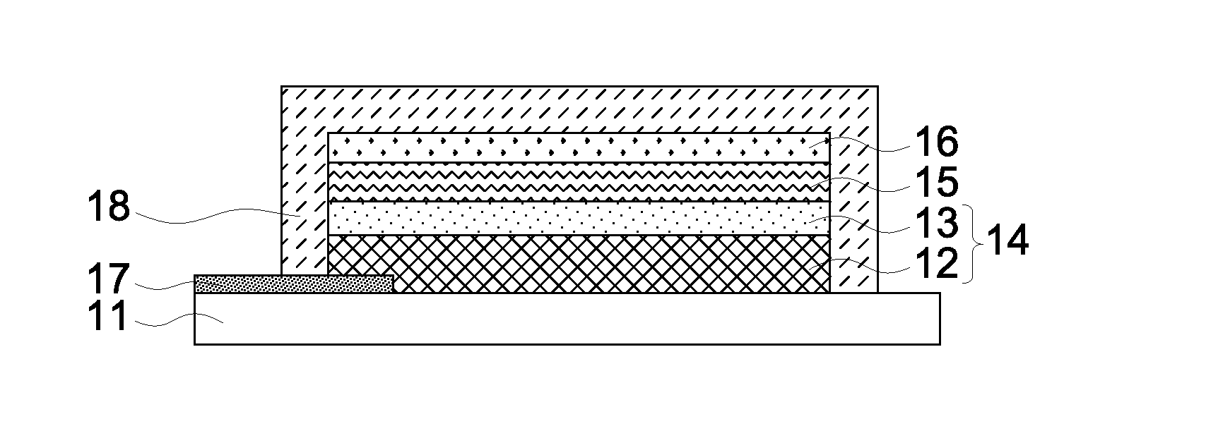
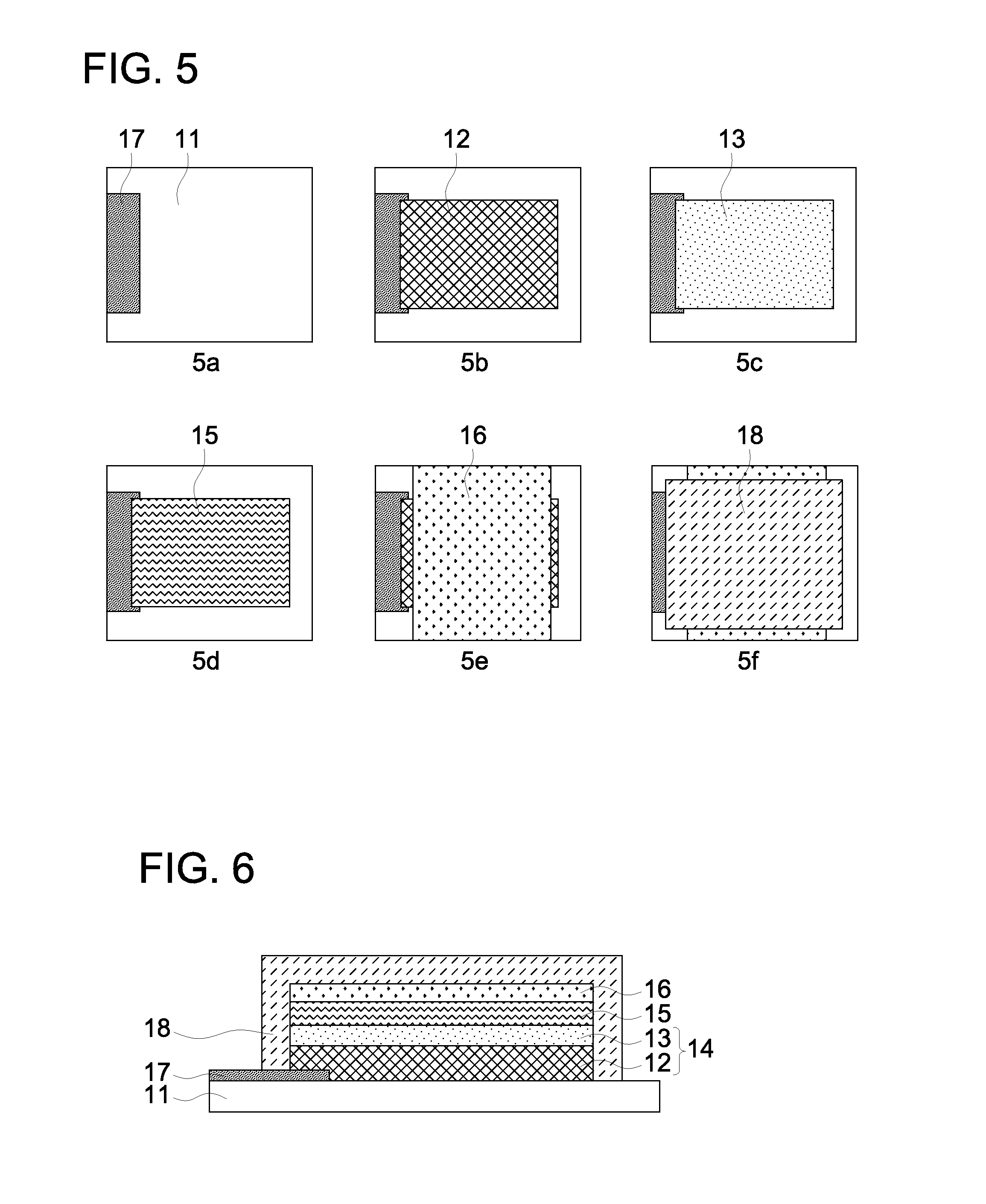
[0141]The thickness of second conductive layer of Electrodes 1-30 and the used conductive polymers and non-conductive polymers are shown in Table 1. Electrodes 16, 20, 21, 24, 26 and 28 was provided with a third conductive layer which was prepared on a PET film with a silver nanowire dispersion liquid coated with a spin coater so that the coating amount of silver nanowires became 0.06 g / m2 followed by drying. Then a first and a second conductive layer were formed thereon.

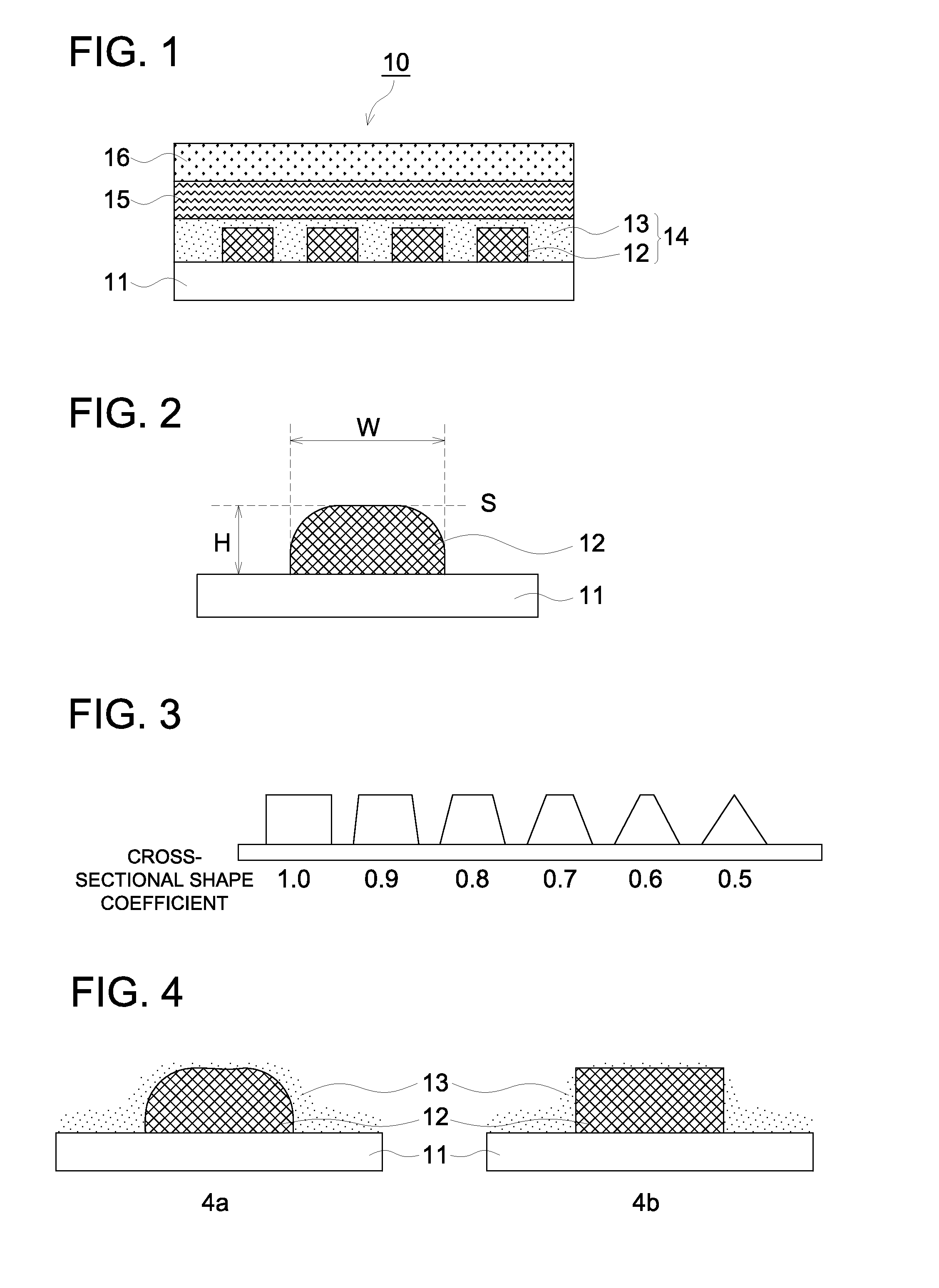
[0142]The shape evaluation of the first conductive layer was done using a laser microscope. The height, the width and the cross-sectional shape of the fine wire were measured and they were evaluated as an average value of 20 points.

[0143]There were evaluated conductivity and transparency of the first conductive layer, and the second conductive layer and the portion which was laminated with the third conductive layer according to the following.

(Transparency)

[0144]Total light transmissivity was measured using HAZE MET...


PUM


Abstract

Disclosed is a transparent electrode which is configured of a first conductive layer that is composed of a metal or metal oxide fine wire that is formed in a pattern on a substrate; and a second conductive layer that covers the first conductive layer and contains a conductive polymer. The transparent electrode is characterized in that the fine wire of the first conductive layer satisfies the conditions mentioned below. Also disclosed is an organic electronic element Line width (W): 20-200 μm Height (H): 0.2-2.0 μm Aspect ratio: 0.001<H/W≦0.1 Coefficient of cross-sectional shape: 0.6<S/(W·H)<0.9 (In this connection, S represents the cross-sectional area of the conductive layer.)

Description

TECHNICAL HELD[0001]The present invention relates to an organic electronic element such as an organic electroluminescence element (hereafter, it is called as an organic EL element) or an organic solar cell. In particular, the present invention relates to an organic electronic element having achieved improved element properties of driving voltage; efficiency; and lifetime.BACKGROUND[0002]In recent years, it has been focused attention on an organic electronic element such as an organic EL element or an organic solar cell. In these elements, a transparent electrode has became one of indispensable composing technologies.[0003]Conventionally, as a transparent electrode, there has been mainly used an ITO transparent electrode having an indium-tin complex oxide (ITO) membrane produced by a vacuum deposition method or a sputtering process on transparent substrates, such as glass and a transparent plastic film. However, there were problems that a manufacturing cost was high since the metal o...

Claims


Application Information

Patent Timeline
IPC IPC(8): H05K1/02H05K1/09
CPCH01L51/5212H01L51/5215Y02E10/549H01L51/0085H01L51/0022Y10T428/25Y10T428/31678H10K71/611H10K85/342H10K50/814H10K50/816H05K1/02H05K1/09
Inventor TAKEDA, AKIHIKOKOYAMA, HIROKAZU
Owner MERCK PATENT GMBH
Why Eureka
Try Eureka