Catalysts for feedstock-flexible and process-flexible hydrogen production

a technology of catalysts and hydrogen production, applied in the field of catalysts, can solve the problem of small catalyst needed per unit amount of hydrogen produced, and achieve the effect of high activeness

Inactive Publication Date: 2013-03-07
UNIVERSITY OF REGINA
View PDF3 Cites 14 Cited by
  • Summary
  • Abstract
  • Description
  • Claims
  • Application Information

AI Technical Summary

Benefits of technology

[0004]There is strong interest and advantage in developing novel, highly active, stable catalysts for H2 production from either biomass-derived or fossil f...

Problems solved by technology

Consequently, the amount of catalyst neede...

Method used


Image

  • Catalysts for feedstock-flexible and process-flexible hydrogen production
  • Catalysts for feedstock-flexible and process-flexible hydrogen production
  • Catalysts for feedstock-flexible and process-flexible hydrogen production

Examples


example 1

Preparation of Ternary & Quaternary Mixed Oxide Supports

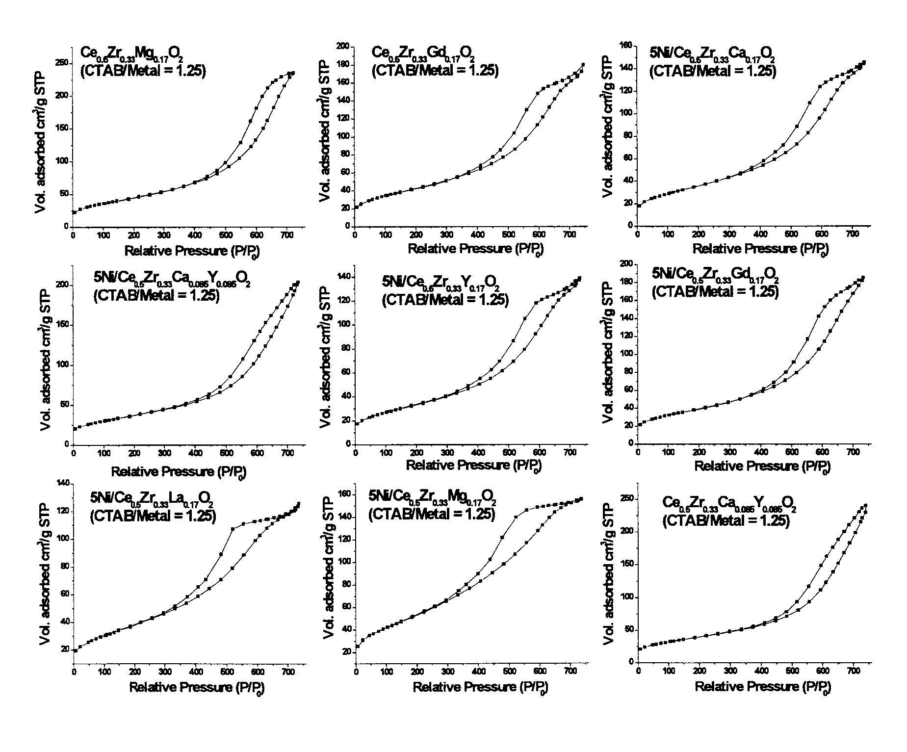
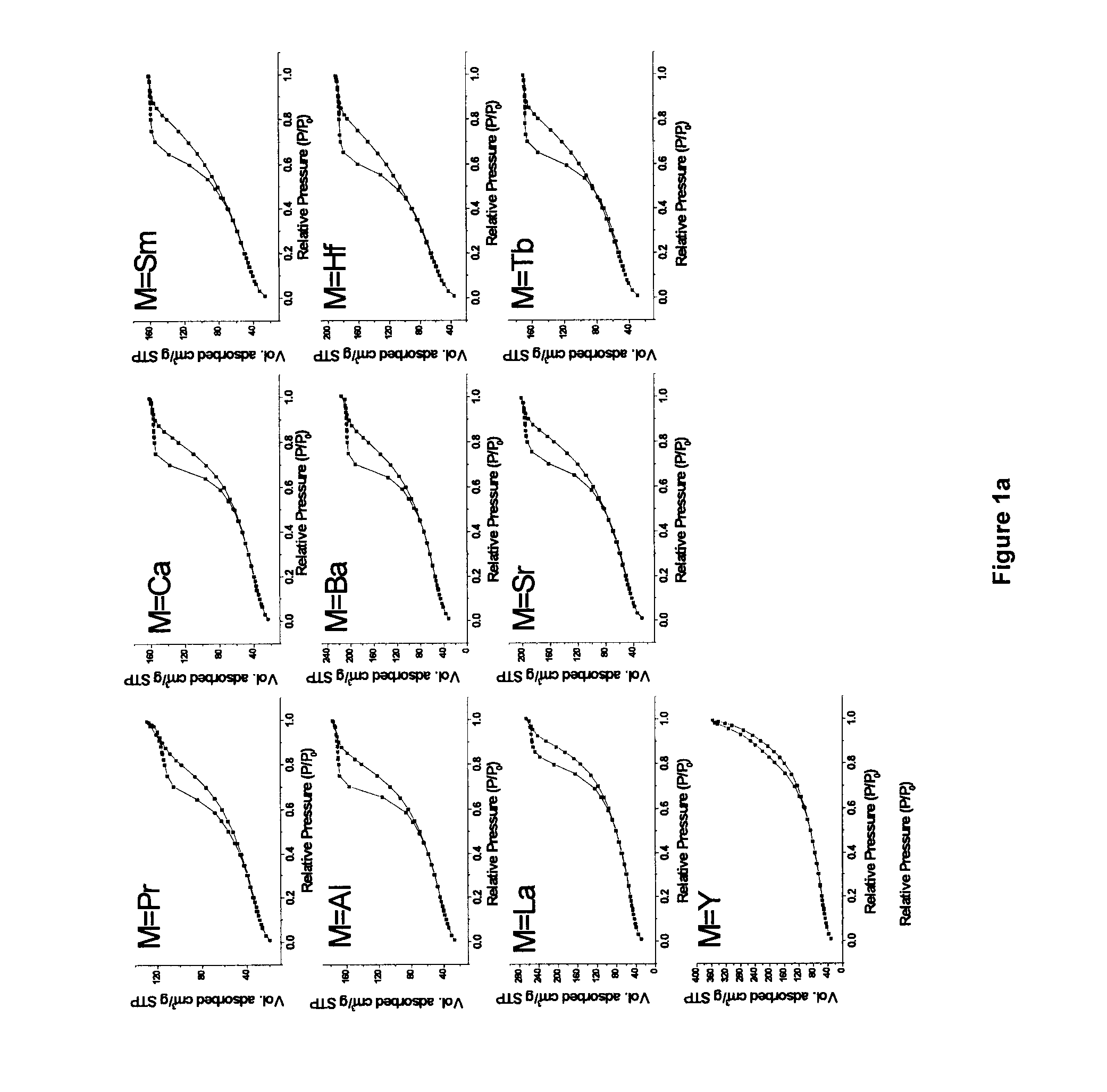
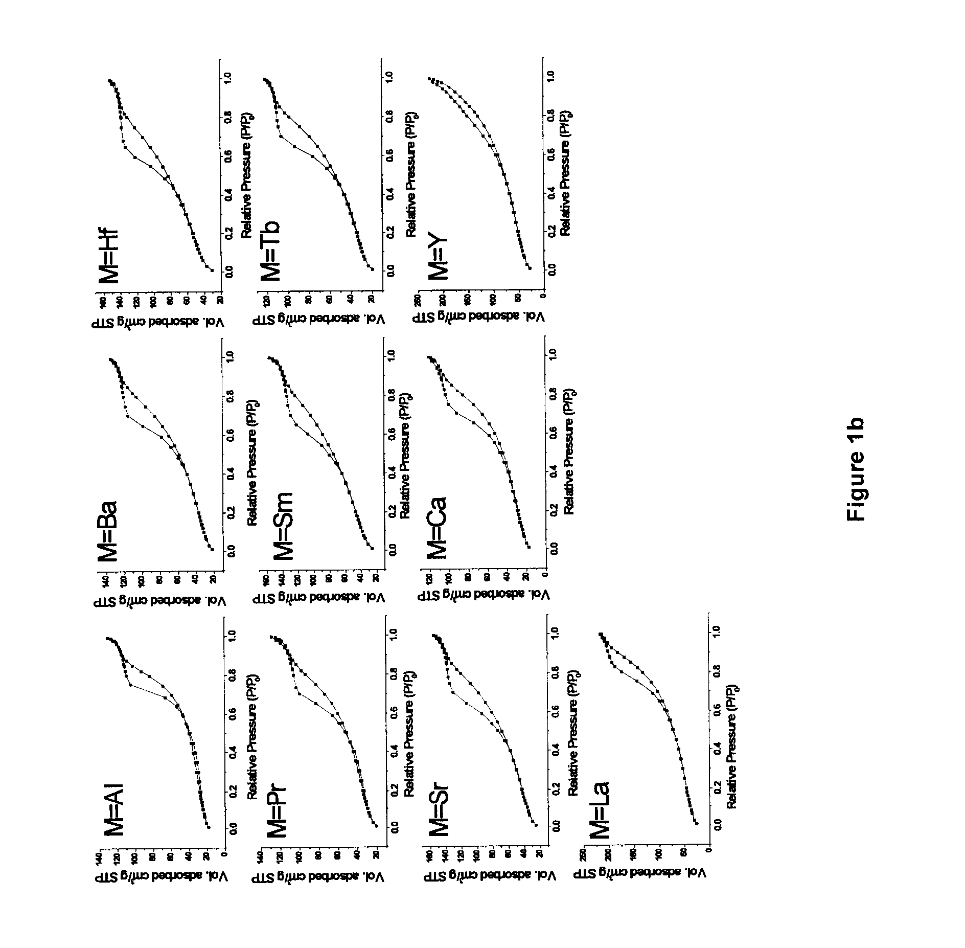
[0108]The synthetic route employed in the study, is based on a modification of a ‘surfactant assisted route’ used by Idem et al. [2006] for binary oxide supports [21], wherein nitrate salts of different metal ions were hydrolyzed together along with a surfactant (CTAB) under basic conditions, and subsequently aged hydrothermally under autogenous pressure at 90° C. for 60 h. The CTAB / [Ce+Zr] ratio of 1.25 was used in the previous report [21]. In most of the current work, the surfactant (CTAB) usage is significantly reduced by a factor of 2.5 for the purpose of minimizing wastes generated during catalyst making. This represents a much improved and optimized version of the previous recipe [21]. Binary oxide supports (Ce0.6Zr0.4O2) with CTAB / [Ce+Zr] molar ratios 0.5 and 1.25 were also prepared in the current study for comparison purposes. The two binary oxide supports prepared using two different CTAB / [Ce+Zr] ratios are abbre...

example 2

Preparation of Supported Nickel Oxide Catalysts

[0127]A nominal 5 wt. % Ni was loaded over the above-prepared supports (I) (refer to paragraph [00100]) by standard wet impregnation method. Similarly the binary oxide supports CZ(0.5) and CZ(1.25) were also impregnated by same procedure to yield corresponding catalysts i.e., NZC(0.5) and NCZ(1.25). In a typical impregnation 14.25 g of catalyst support (I) is immersed in 127.75 ml of 0.1 M Ni(NO3)2 solution. The mixture was subjected to slow heating under constant stirring in a hot water bath, so as to remove the excess water; the dried powders thus obtained were calcined at 650° C. in air for 3 h. The calcined catalysts are reduced in situ during the course of reaction in order to reduce the NiO species to metallic Ni species. The reduction is carried out at 700° C. in flowing 5% H2 / bal.N2.

example 3

Catalyst Characterization

[0128]a. Surface Area and Pore Size Distribution Analysis

[0129]The BET surface area and pore size distribution analyses for all catalysts were obtained by N2 physisorption at liquid N2 temperature using a Micromeritics ASAP 2010 apparatus. Prior to analysis, all the samples were degassed for 6 h at 180° C. under vacuum. Pore size distribution and average pore volume were analyzed using the desorption branch of the N2-isotherm. Each sample was analyzed by N2 physisorption at least twice in order to establish repeatability. The error in these measurements was ≦1%.

b. XRD Measurements

[0130]Powder XRD patterns were recorded on a Bruker Discover diffractometer using nickel-filtered CuKα (0.154056 nm) as the radiation source. The intensity data were collected over a 2θ range of 10-90° with a step size of 0.02° using a counting time of 1 s per point. Crystalline phases were identified through comparison with the reference data from ICDD files [22].

c. TPR Measurement...


PUM

PropertyMeasurementUnit
Fractionaaaaaaaaaa
Fractionaaaaaaaaaa
Fractionaaaaaaaaaa

Abstract

A series of ternary oxide and quaternary oxide catalysts were prepared and evaluated for various reforming processes. Representative examples of these catalysts were found to be active and stable for all the processes tested verifying the “feedstock and process flexible” nature of these catalysts. Thus, feedstock- and process-flexible reforming catalysts for hydrogen and/or syngas production have been developed.

Description

FIELD OF THE APPLICATION[0001]The present application is in the field of catalysts for the conversion of fuel-based (both fossil & biomass derived) feedstocks into hydrogen.BACKGROUND OF THE APPLICATION[0002]One of the advantages of hydrogen gas (H2) as an energy carrier is that it carries a high energy per unit mass (one kg of hydrogen has approximately the same energy content, as that of 1 gallon / 2.7 kg of gasoline), thus potentially facilitating energy portability [1]. In addition, pure hydrogen is a non-polluting fuel, producing only water vapor at its point of use, so that pollutants will not be dispersed throughout a hydrogen energy economy but will primarily be localized where hydrogen and other elements of the energy system are produced. Hydrogen can be produced from a wide variety of primary energy sources and different production technologies or processes [2]. At present, nearly all of the worldwide production of hydrogen gas (H2) is from steam reforming of natural gas. Th...

Claims


Application Information

Patent Timeline
IPC IPC(8): C01B3/02C01B3/32C01B3/40B01J23/10B01J23/83
CPCB01J23/10B01J23/755C01B2203/1235C01B2203/1211C01B2203/1082C01B2203/1041C01B2203/1011C01B2203/0261C01B2203/0244C01B2203/0238C01B2203/0233C01B3/40C01B3/326B01J2523/00B01J37/18B01J37/10B01J37/08B01J37/036B01J37/033B01J23/83B01J35/002B01J37/0201B01J2523/23B01J2523/3712B01J2523/48B01J2523/31B01J2523/25B01J2523/375B01J2523/49B01J2523/3706B01J2523/22B01J2523/3718B01J2523/3737B01J2523/24B01J2523/3756B01J2523/36Y02P20/52
Inventor IDEM, RAPHAELMOHAMMED, ATAULLAH KHANIBRAHIM, HUSSAMELDINTONTIWACHWUTHIKUL, PAITOONSUKONKET, THITINATKHAN, MOHAMMED FAYSAL AHAMEDSENGUPTA, PROTYAIZAHID, MOHAMMED ABUSAHA, BAPPY
Owner UNIVERSITY OF REGINA
Why Eureka
Try Eureka