
Reflective mask blank, reflective mask and method of manufacturing reflective mask

a reflective mask and blank technology, applied in the field of reflective mask blanks, reflective masks, and reflective mask manufacturing methods, can solve the problems of inability to obtain etching rates sufficient for forming transfer patterns, detrimental effects on the surface of absorber films, and inability to obtain transfer patterns. , to achieve the effect of favorable optical properties, favorable optical properties, and high transfer patterns

Active Publication Date: 2013-03-28
HOYA CORP
View PDF2 Cites 6 Cited by
  • Summary
  • Abstract
  • Description
  • Claims
  • Application Information

AI Technical Summary

Benefits of technology

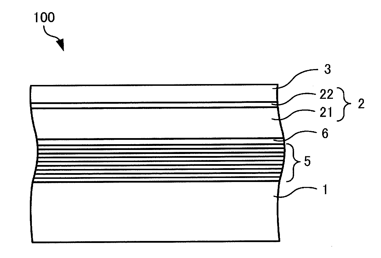
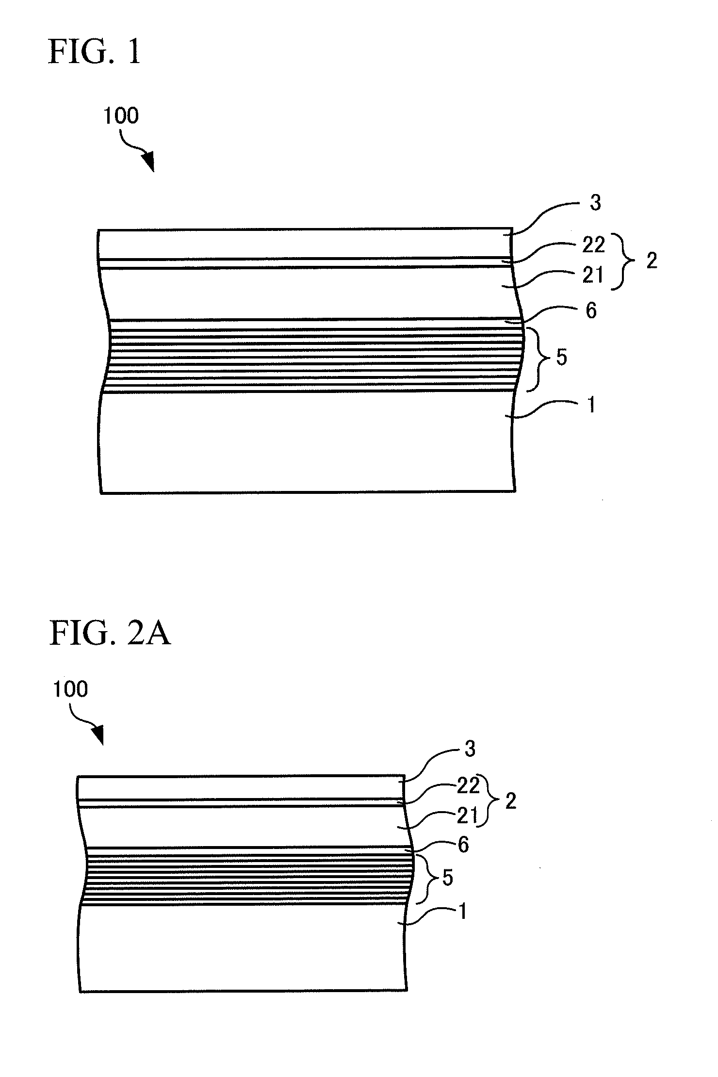
The present invention provides a reflective mask blank that allows for the fabrication of a highly precise reflective mask and an absorber film with good optical properties using a reflective mask blank made by laminating an absorber film of tantalum and an etching mask film of chromium. The reflective mask blank has an absorber film with a highly oxidized layer that has a maximum peak at a binding energy of more than 23 eV. The use of this reflective mask blank allows for the fabrication of a reflective mask with favorable optical properties even after removing the etching mask film. Additionally, the reflective mask made from this blank has favorable line edge roughness of the transfer pattern formed in the absorber film.

Problems solved by technology

In the case of producing this reflective mask, it was found that there were unique problems to tantalum-based materials in the case of examining the use of a reflective mask blank obtained by laminating a multilayer reflective film that reflects EUV light, an absorber film composed of a tantalum-based material, an etching mask film composed of a chromium-based material, and a resist film composed of an organic material on a substrate.
However, in the case of carrying out dry etching on a tantalum-based material that demonstrates extensive bonding with oxygen (oxygen content in the material is high) using a chlorine-based gas that does not contain oxygen, an etching rate sufficient for forming a transfer pattern is unable to be obtained.
However, when the etching mask film is removed after having formed the transfer pattern on the absorber film, it was determined that there is a detrimental effect on the surface of the absorber film or the edges of the pattern of the absorber film become rounded.
This problem occurs in the case the etching mask film is stripped by dry etching using a mixed gas of a chlorine-based gas and oxygen gas.

Method used


Image

  • Reflective mask blank, reflective mask and method of manufacturing reflective mask
  • Reflective mask blank, reflective mask and method of manufacturing reflective mask
  • Reflective mask blank, reflective mask and method of manufacturing reflective mask

Examples


example 1

[0177][Production of Reflective Mask Blank]

[0178]A substrate was prepared that was composed of SiO2—TiO2 glass having vertical and horizontal dimensions of about 152 mm×152 mm and having a thickness of about 6.25 mm. The edge faces and main surface of this substrate 1 were polished to a prescribed surface roughness (root mean square roughness Rq: not more than 0.15 nm), followed by carrying out prescribed washing treatment and drying treatment.

[0179]Next, the transparent substrate 1 was installed in an ion beam sputtering apparatus and the multilayer reflective film 5 was deposited by ion beam sputtering using a Si target and Mo target. More specifically, a 4.2 nm Si film was deposited after laminating 40 periods consisting of a 4.2 nm Si film and 2.8 nm Mo film. Continuing, the substrate 1 on which the multilayer reflective film 5 was formed was installed in a single-wafer DC sputtering apparatus, and the protective layer 6 composed of RuNb was formed to a thickness of 2.5 nm on th...

example 2

[0187][Production of Reflective Mask Blank]

[0188]The reflective mask blank of Example 2 was fabricated according to the same procedure as Example 1 with the exception of changing the material of the etching mask film 3 to CrO (Cr: 46 at %, O: 54 at %) and changing the layer thickness to 6 nm.

[0189][Production of Reflective Mask]

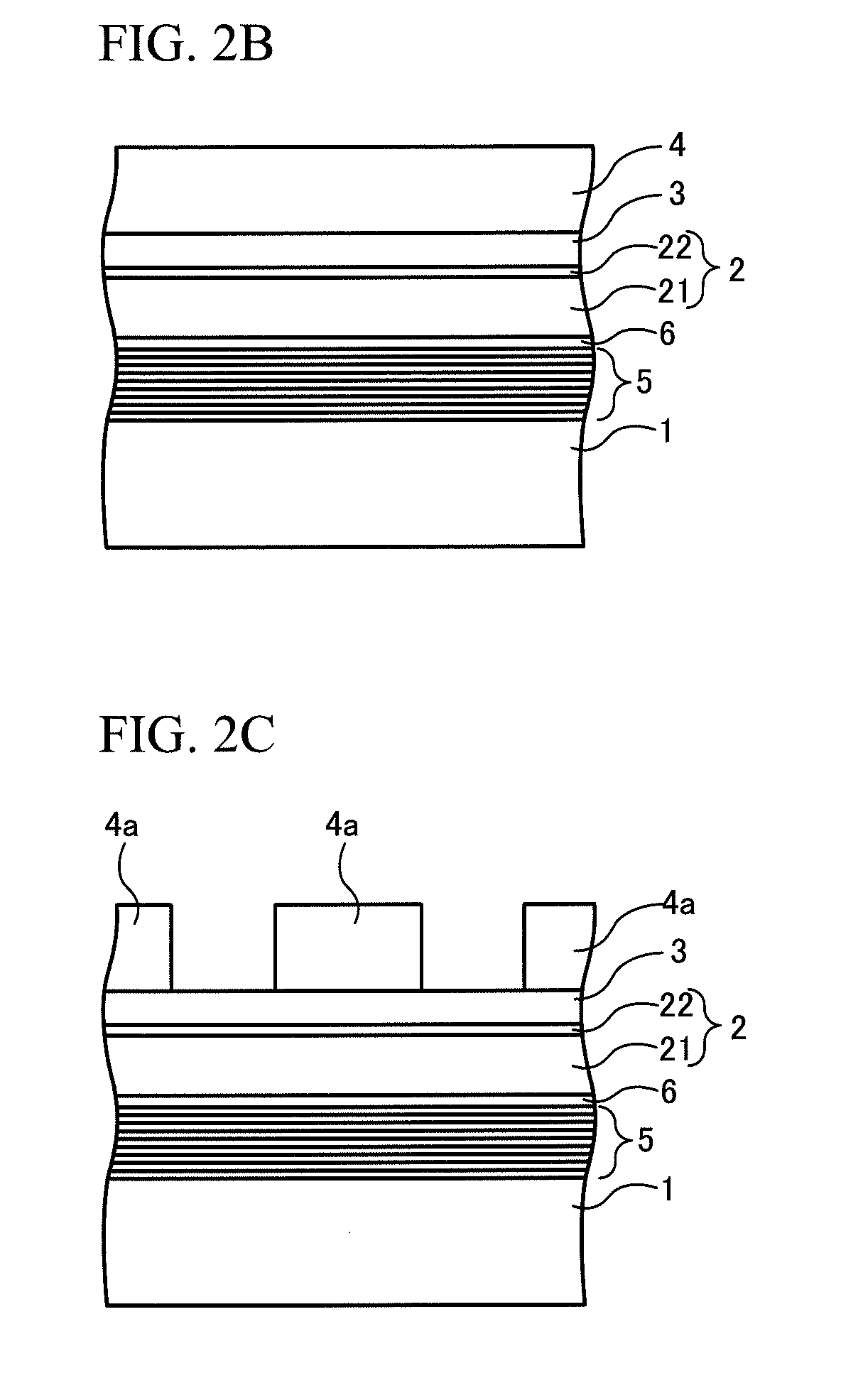
[0190]Next, the reflective mask 201 of Example 2 was fabricated according to the following procedure using the reflective mask blank 101 of Example 2. First, the resist film 4 composed of a chemically amplified resist for electron beam lithography was formed at a layer thickness of 60 nm on the etching mask film 3 by spin coating (see FIG. 4B). Next, the resist pattern 4a was formed in the resist film 4 by electron beam drawing followed by carrying out prescribed development treatment and washing treatment (see FIG. 4C). Furthermore, the transfer pattern formed by electron beam lithography had a 22 nm node fine pattern. Next, a transfer pattern (etching mask ...

example 3

[0192][Production of Reflective Mask Blank]

[0193]The reflective mask blank of Example 3 was fabricated according to the same procedure as Example 1 with the exception of carrying out the process for forming the highly oxidized layer 242 on the upper layer 24 of the absorber film 2 by ozone water treatment instead of hot water treatment. Ozone water treatment (surface treatment) was carried out by applying ozone-containing water having an ozone concentration of 50 ppm and temperature of 25° C. under the condition of a treatment time of 15 minutes.

[0194]The absorber film 2 was measured by Auger electron spectroscopy (AES) after the ozone water treatment. From the results, it was confirmed that the highly oxidized layer 242 was formed at a thickness of 2 nm on the surface layer of the upper layer 24. The oxygen content of this highly oxidized layer 242 was 71.4 at % to 67 at %. The compositions and optical properties of each of the other layers of the absorber film 2 were the same as t...


PUM


Abstract

The present invention is a reflective mask blank used to fabricate a reflective mask, which has a laminated structure of a multilayer reflective film, an absorber film and an etching mask film in this order on a substrate, wherein the etching mask film comprises a material containing chromium, the absorber film comprises a material containing tantalum, a highly oxidized layer is formed on the surface layer of the absorber film on the opposite side from the substrate, and a Ta 4f narrow spectrum of the highly oxidized layer when analyzed by X-ray photoelectron spectroscopy has a maximum peak at a binding energy of more than 23 eV.

Description

TECHNICAL FIELD[0001]The present invention relates to a reflective mask blank, a reflective mask, and method of manufacturing a reflective mask.BACKGROUND ART[0002]Recently in the semiconductor industry, EUV lithography, which is an exposure technology that uses extreme ultraviolet (EUV) light, is considered to be promising accompanying the miniaturization of semiconductor devices. EUV light refers to light of a wavelength band of the soft X-ray region or vacuum ultraviolet region, and more specifically, refers to light having a wavelength of about 0.2 nm to 100 nm. Examples of transfer masks proposed for use in this EUV lithography include the reflective exposure mask described in Patent Literature 1 (JP-A-2002-246299) and the reflective photomask described in Patent Literature 2 (JP-A-2010-192503).[0003]On the other hand, miniaturization of transfer patterns formed on light shielding layers has become remarkable in recent years even in the case of binary masks used in lithography ...

Claims


Application Information

Patent Timeline
IPC IPC(8): G03F1/24
CPCG03F1/58G03F1/24G03F1/80
Inventor SAKAI, KAZUYAOHKUBO, RYONOZAWA, OSAMUSUZUKI, TOSHIYUKI
Owner HOYA CORP
Learn More