

System and Methods for Wastewater and Produced Water Cleaning and Reclamation
a technology for producing water and wastewater, applied in the field of water purification, can solve the problems of exacerbated surface land use and water waste issues, outcry and loss of social-license-to-operate, and contamination of borehole-produced water
- Summary
- Abstract
- Description
- Claims
- Application Information
AI Technical Summary
Benefits of technology
Problems solved by technology
Method used
Image

Examples
example 1
Treatment of a Produced Water Stream
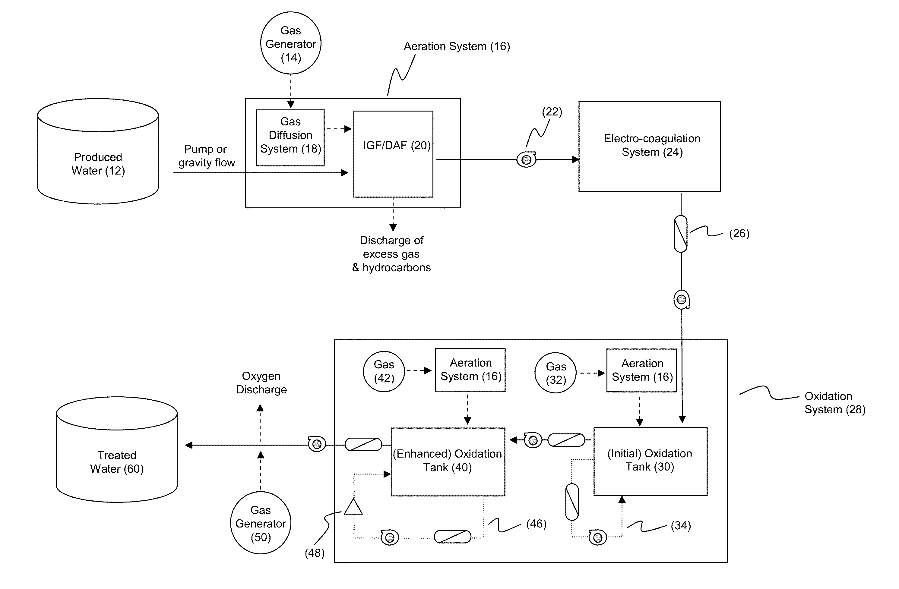
[0059]A produced water stream may be purified by passing the waste stream through a series of treatment “stages”, each stage acting in concert to separate various impurities within the initial produced water stream. This general process of purification is illustrated schematically in FIG. 3. Initially, the stream of produced water (12) enters a gas-induced hydrocarbon separation stage, wherein oil entrained within the fluid stream is separated from the water using an inert gas, such as nitrogen (N2) or carbon dioxide (CO2) gas delivered from tanks or a gas generator (14), using an aeration system (20) that may be any system suitable for and capable of creating and delivering very small (e.g., ranging from about 1 μm to about 10 μm, preferably about 5 μm) gas bubbles into the fluid flow stream in order to enhance the oil recovery of the produced water, and remove a bulk of the hydrocarbons. As depicted in the figure, the aeration system (16) may co...
example 2
Treatment of a Fracturing Flow-Back Water
[0066]Generally, fracturing flow-back water (also referred to as “frac flow-back water”) contains a high concentration of dissolved minerals as a consequence of the fracturing process itself. Typically, while the fracturing flow-back fluid is heavier in salts and dissolved metals than produced water, it may or may not contain hydrocarbons, depending upon whether it was taken from an oil or a gas well.
[0067]The general process of purification for fracturing fluid flow-back water is generally the same as that outlined above regarding the purification of produced water. Initially, the fracturing fluid flow-back water stream is contacted with a gas-induced hydrocarbon separation stage, wherein oil entrained within the fluid stream is separated from the water using an inert gas, such as nitrogen (N2) gas delivered from tanks or a gas generator, using a diffused air flotation (DAF) system. As above, this system acts to diffuse very small (e.g., ran...
example 3
Treatment of an Aqueous Drilling Fluid
[0071]This is similar to the process described above concerning the treatment of fracturing fluids, with the possible addition of further recirculation or passing over EC plates a plurality (two or more) of times, due to the presence of the additional solids (mostly clays and silts).
[0072]As is evident from the prophetic process examples discussed above, it is evident that the methods described herein have great flexibility due in part to the variety of gases that can be employed within the overall process to achieve various results. In general terms, the process can employ both inert and reactive other gases to achieve various purposes, as appropriate. For example, while nitrogen gas (N2) would generally be used to separate hydrocarbons from the water, carbon dioxide (CO2) may be also be used as a reactive gas, as may methane (CH4) and hydrogen (H2).
[0073]Other and further embodiments utilizing one or more aspects of the inventions described ab...
PUM
| Property | Measurement | Unit |
|---|---|---|
| Temperature | aaaaa | aaaaa |
| Temperature | aaaaa | aaaaa |
| Pressure | aaaaa | aaaaa |
Abstract
Description
Claims
Application Information