Saw blade and method for multiple sawing of rare earth magnet

a rare earth magnet and sawing blade technology, applied in the direction of gear teeth, manufacturing tools, manufacturing apparatus, etc., can solve the problems of low productivity of sawing technology using id blades, parts cannot be formed, and lowering manufacturing yield, so as to improve sawing accuracy, reduce cutting resistance, and high accuracy

Inactive Publication Date: 2013-05-30
SHIN ETSU CHEM IND CO LTD
View PDF6 Cites 4 Cited by
  • Summary
  • Abstract
  • Description
  • Claims
  • Application Information

AI Technical Summary

Benefits of technology

[0018]The saw blades in the form of a resinoid wheel are used in multiple sawing of a rare earth magnet block into multiple pieces. As compared with the prior art, the saw blade reduces the cutting resistance, improves the sawing accuracy, and ensures sawing at a high accuracy and high speed even if the saw blade is thinner than the conventional blades. The blade is of great worth in the industry.

Problems solved by technology

However, when it is desired to manufacture parts of small size or parts having a reduced thickness in magnetization direction, the sequence of press molding and sintering is difficult to form sintered parts of normal shape, leading to a lowering of manufacturing yield, and at worst, such parts cannot be formed.
The sawing technology using ID blades is low in productivity because of a single blade cutting mode.
However, in an attempt to saw a hard material such as rare earth magnet by a thin OD blade, the prior art core of alloy tool steel is short in mechanical strength and becomes deformed or bowed during sawing operation, losing dimensional accuracy.
However, if a high frictional resistance is exerted between the cutting part and the magnet during sawing of the magnet, high accuracy machining is not expected.
Then, even if the cemented carbide core is used, chipping and / or bowing can occur, adversely affecting the machined state.
However, since the space between the saw blade and the workpiece or rare earth magnet is extremely narrow, it is difficult to effectively supply the coolant between the saw blade and the magnet.

Method used


Image

  • Saw blade and method for multiple sawing of rare earth magnet
  • Saw blade and method for multiple sawing of rare earth magnet
  • Saw blade and method for multiple sawing of rare earth magnet

Examples


example 1

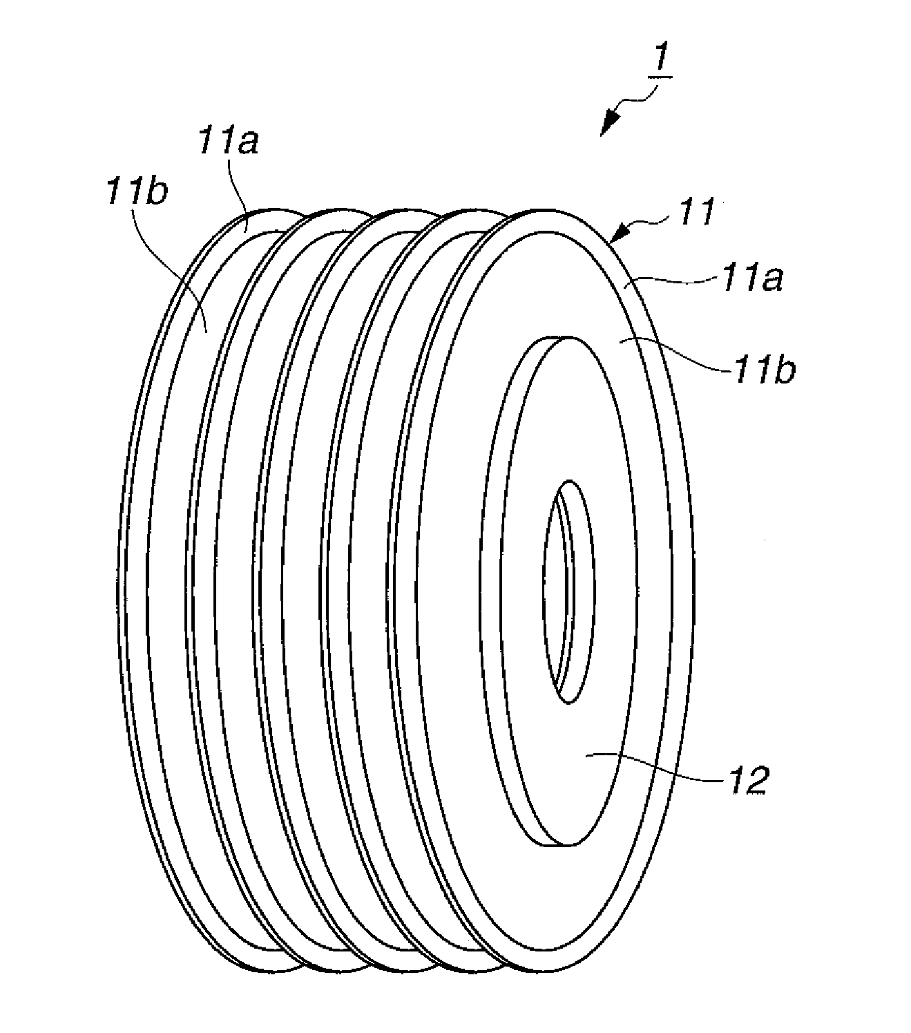
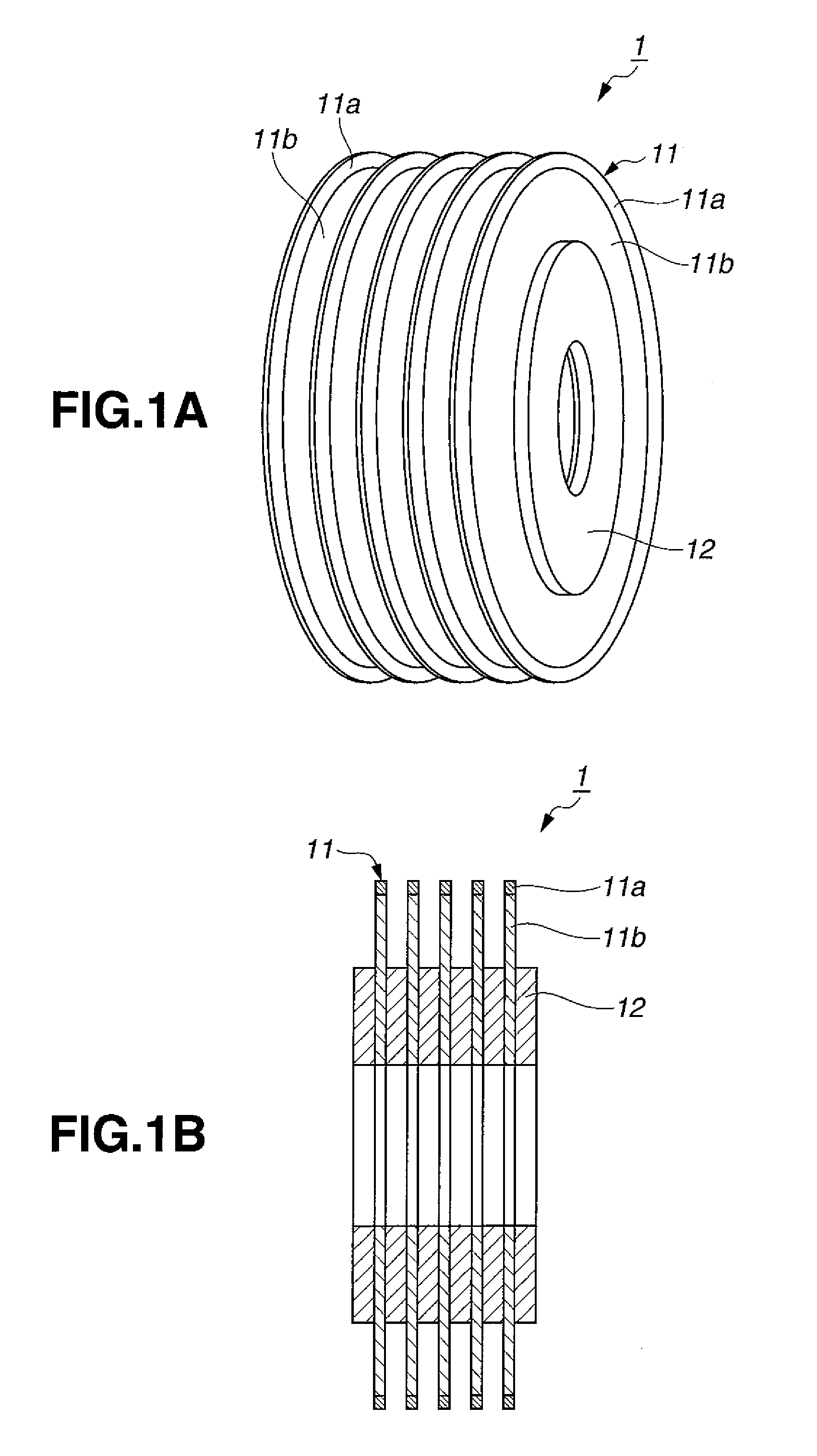
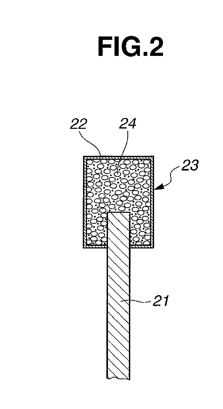
[0036]OD blades were fabricated by providing a doughnut-shaped disk core of cemented carbide (consisting of WC 90 wt % / Co 10 wt %) having an outer diameter 120 mm, inner diameter 40 mm, and thickness 0.3 mm, and heat pressing a composition to an outer peripheral rim of the core to form a resinoid grinding wheel section or cutting part. The composition contained 10 wt % of graphite having a particle size of 5 to 30 μm as the lubricant, 40 wt % of #800 SiC (GC powder) as the matrix, 25 wt % of a phenol formaldehyde resin as the binder, and 25 wt % of synthetic diamond grains having an average particle size of 150 μm. Subsequent finish work completed OD blades (or sawing abrasive blades). The axial extension of the cutting part from the core was 0.05 mm on each side, that is, the cutting part had a width of 0.4 mm (in the thickness direction of the core). The radial extension or length of the cutting part is 2.5 mm, that is, the blade had an outer diameter of 125 mm.

[0037]Using the OD ...


PUM

PropertyMeasurementUnit
particle sizeaaaaaaaaaa

Abstract

A multiple blade assembly comprising a plurality of spaced apart saw blades mounted on a rotating shaft is used for sawing a rare earth magnet block into multiple pieces by rotating the plurality of saw blades. The saw blade comprises a core in the form of a thin doughnut disk and a peripheral cutting part on an outer peripheral rim of the core. The cutting part is made of a composition comprising an abrasive, a resin binder, and a lubricant.

Description

CROSS-REFERENCE TO RELATED APPLICATION[0001]This non-provisional application claims priority under 35 U.S.C. §119(a) on Patent Application No. 2011-259157 filed in Japan on Nov. 28, 2011, the entire contents of which are hereby incorporated by reference.TECHNICAL FIELD[0002]This invention generally relates to a method for sawing a magnet block into multiple pieces. More particularly, it relates to a saw blade for use in sawing a rare earth magnet block into multiple pieces.BACKGROUND ART[0003]Systems for manufacturing commercial products of rare earth magnet include a single part system wherein a part of substantially the same shape as the product is produced at the stage of press molding, and a multiple part system wherein once a large block is molded, it is divided into a plurality of parts by machining. The single part system includes press molding, sintering or heat treating, and finishing steps. A molded part, a sintered or heat treated part, and a finished part (or product) ar...

Claims


Application Information

Patent Timeline
Patent Type & Authority Applications(United States)
IPC IPC(8): B24D5/12B24B1/00
CPCB24B1/00B24D3/346B28D5/029B24D5/12B26D1/14B28D1/24B24B27/06
Inventor SATO, KOJIURAKI, YASUNORI
Owner SHIN ETSU CHEM IND CO LTD
Why Eureka
Try Eureka