Process for production of (rare earth)-mg-ni-based hydrogen storage alloy

Active Publication Date: 2013-06-06
SANTOKU CORP
View PDF1 Cites 1 Cited by
  • Summary
  • Abstract
  • Description
  • Claims
  • Application Information

AI Technical Summary

Benefits of technology

The present invention provides a safe and industrially advantageous method for producing a rare earth-Mg-Ni based hydrogen storage alloy with excellent cycle characteristics, high initial activity and large capacity. The alloy has uniform distribution of its constituent elements and excellent corrosion resistance. This method also allows for the production of a nickel-hydrogen rechargeable battery with outstanding battery characteristics. Additionally, the invention provides an anode for a nickel-hydrogen rechargeable battery employing the alloy and a nickel-hydrogen rechargeable battery with the anode.

Problems solved by technology

This makes the compositional control of the alloy difficult.
Further, the melting furnace is filled with Mg vapor, so that the situation in the furnace cannot be grasped, which is dangerous.
Generation of Mg vapor is also accompanied by generation of dust, which may cause dust explosion.
Thus melting at above the boiling point of Mg involves profound danger.
However, this process makes it difficult to obtain an alloy of homogeneous composition, in particular a low-Mg alloy of homogeneous composition.

Method used


Image

  • Process for production of (rare earth)-mg-ni-based hydrogen storage alloy
  • Process for production of (rare earth)-mg-ni-based hydrogen storage alloy
  • Process for production of (rare earth)-mg-ni-based hydrogen storage alloy

Examples


example 1

[0070]Starting materials other than Mg were measured out, and melted in a high-frequency melting furnace in an argon gas atmosphere into an alloy melt. The alloy melt was rapidly cooled and solidified by strip casting with a single-roll casting system having a water-cooled copper roll at a pouring temperature of 1400° C., into flakes having an average thickness of 0.4 mm. The obtained flakes were preliminarily pulverized in a ball mill into an alloy having a mean particle diameter (D50) of 75 μm. The composition of the obtained alloy was analyzed by ICP, and found to be La0.60Sm0.16Zr0.04Ni3.45Al0.10. The value of IA / IB=100 of the alloy determined by X-ray diffraction under the above-mentioned conditions was 50%.

[0071]The alloy obtained above was thoroughly mixed with Mg metal powder having a mean particle diameter (D50) of 110 μm in a mortar. The obtained mixture was held in an argon gas atmosphere at 700° C. for 30 minutes, and then at an elevated temperature of 920° C. for 24 hou...

example 2

[0078]An alloy without Mg was prepared in the same way as in Example 1 except that the composition of the starting materials was changed. The composition of the obtained alloy was analyzed by ICP and found to be La0.72Nd0.10Sm0.06Ni3.38Al0.10.

[0079]The obtained alloy was thoroughly mixed with Mg metal powder having a mean particle diameter (D50) of 110 μm in a mortar. The resulting mixture was held in an argon gas atmosphere at 700° C. for 30 minutes, and then at an elevated temperature of 940° C. for 12 hours. The composition of the obtained alloy was analyzed by ICP and found to be La0.72Nd0.10Sm0.06Mg0.12Ni3.38Al0.10. The yield of Mg was 99.5% The melting point of the obtained alloy was about 990° C.

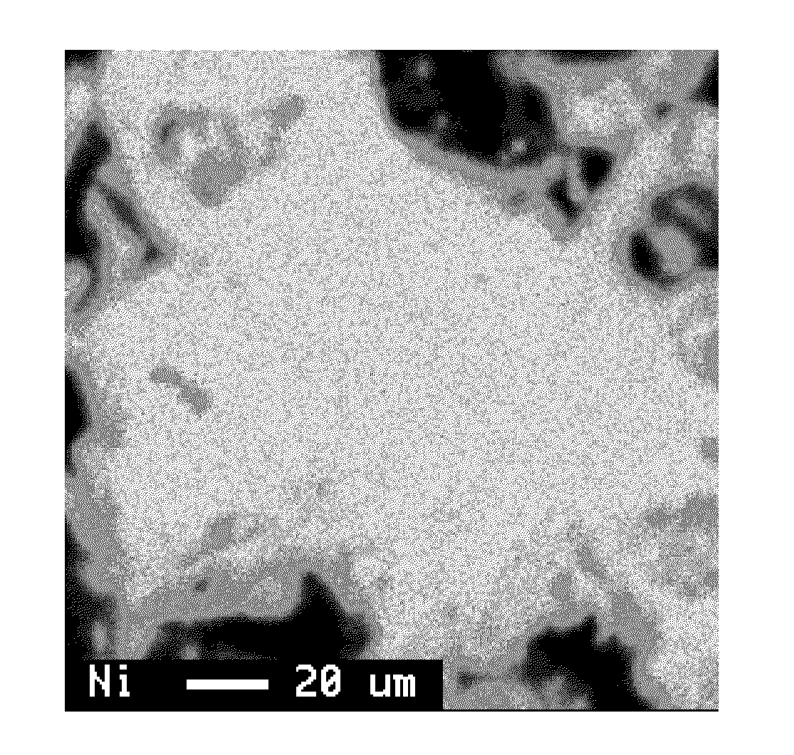
[0080]The Mg elemental mapping image of this alloy is shown in FIG. 2. It is seen that Mg is present more in the surface layer than in the center part. The value of IA / IB×100 of the alloy without Mg and the results of evaluations of the battery characteristics determined in the same w...

example 3

[0081]An alloy without Mg was prepared in the same way as in Example 1 except that the composition of the starting materials was changed. The composition of the obtained alloy was analyzed by ICP and found to be La0.55Ce0.05Sm0.20Ni2.85Al0.15.

[0082]The obtained alloy was thoroughly mixed with Mg metal powder having a mean particle diameter (D50) of 110 μm in a mortar. The resulting mixture was held in an argon gas atmosphere at 700° C. for 30 minutes, and then at an elevated temperature of 940° C. for 12 hours. The composition of the obtained alloy was analyzed by ICP and found to be La0.55Ce0.05Sm0.20Mg0.20Ni2.85Al0.15. The yield of Mg was 100%. The melting point of the obtained alloy was about 950° C.

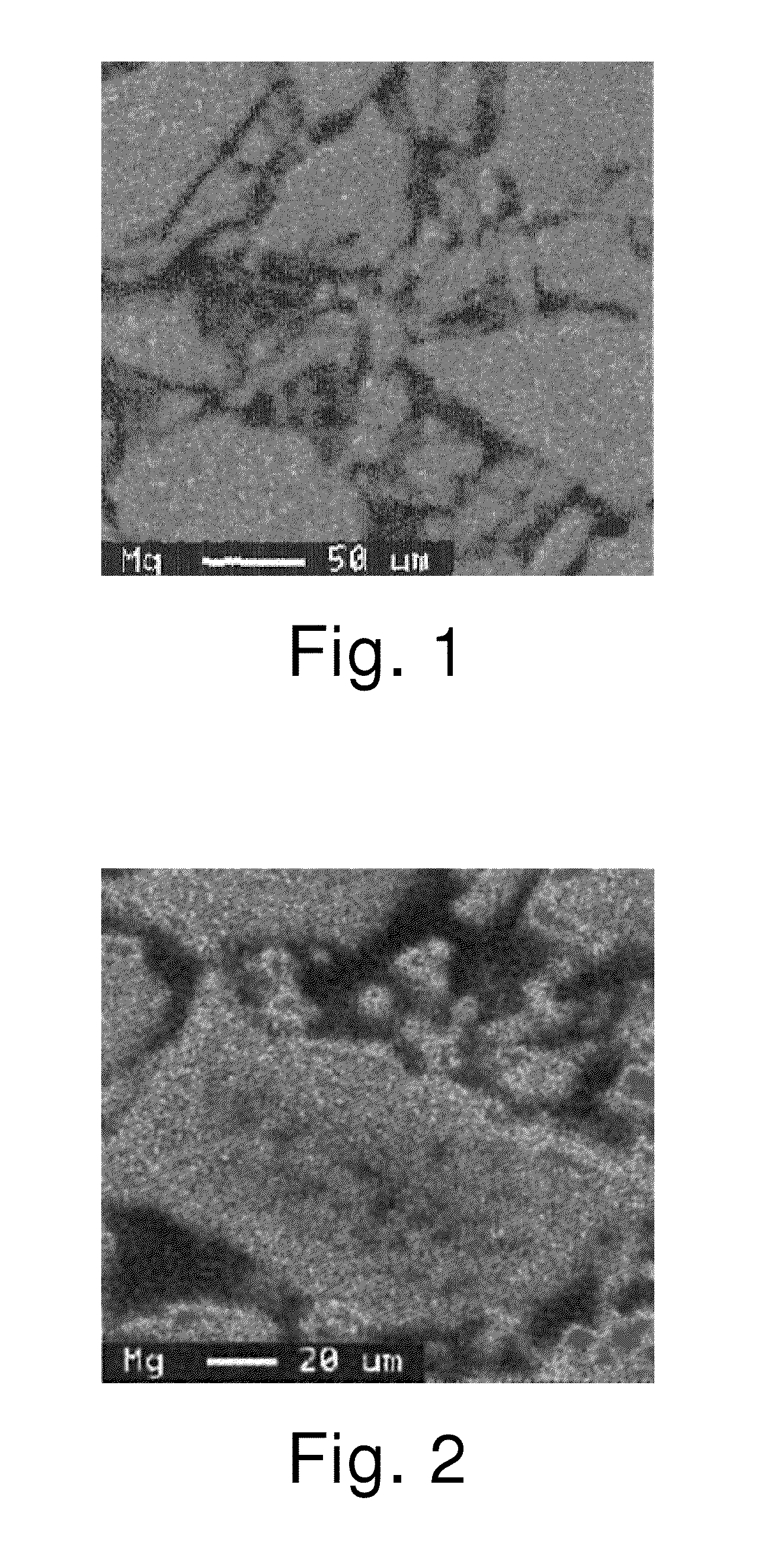
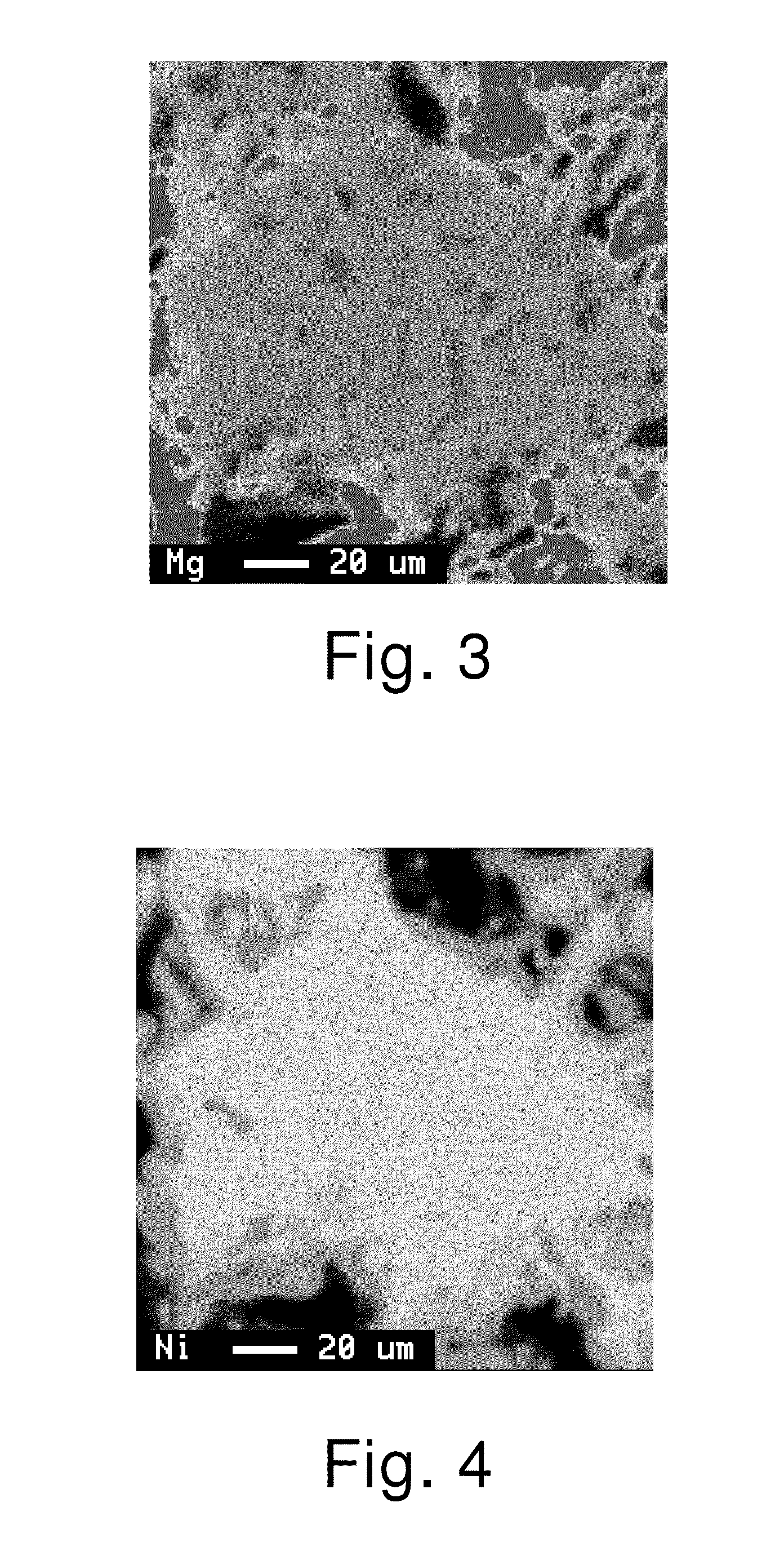
[0083]Observation with an EPMA revealed that Mg was uniformly distributed throughout the alloy. The value of IA / IB×100 of the alloy without Mg and the results of evaluations of the battery characteristics determined in the same way as in Example 1 are shown in Table 1.


PUM

PropertyMeasurementUnit
Temperatureaaaaaaaaaa
Fractionaaaaaaaaaa

Abstract

A safe and industrially advantageous production method is disclosed for producing a rare earth-Mg—Ni based hydrogen storage alloy which realizes production of a nickel-hydrogen rechargeable battery having excellent cycle characteristics and a large capacity. The method is for producing a rare earth-Mg—Ni based hydrogen storage alloy including element A, Mg, and element B, wherein element A is composed of at least one element R selected from rare earth elements including Sc and Y, and optionally at least one element selected from Zr, Hf, and Ca, and element B is composed of Ni and optionally at least one element selected from elements other than element A and Mg. The method includes first step of mixing an alloy consisting of elements A and B and Mg metal and / or a Mg-containing alloy having a melting point not higher than the melting point of Mg metal, and second step of heat-treating a mixture obtained from first step for 0.5 to 240 hours at a temperature 5 to 250° C. lower than a melting point of the rare earth-Mg—Ni based hydrogen storage alloy to be obtained.

Description

FIELD OF ART[0001]The present invention relates to a nickel-hydrogen rechargeable battery, an anode for use in the battery, a rare earth-Mg—Ni based hydrogen storage alloy, and a method for producing the alloy.BACKGROUND ART[0002]A nickel-hydrogen rechargeable battery with an anode containing a hydrogen storage alloy has a higher energy density than a nickel-cadmium rechargeable battery, and places only a small burden on the environment due to absence of toxic Cd. Nickel-hydrogen rechargeable batteries are used in portable devices such as digital cameras and electric tools as well as in electric vehicles and hybrid electric vehicles. Various battery characteristics are desired depending on applications.[0003]As an anode material for a nickel-hydrogen rechargeable battery, hydrogen storage alloys have been developed and used, such as those of LaNi5 type containing AB5 crystals as the main phase, those having a Laves phase as the main phase, and those having a BCC (body-centered cubic...

Claims


Application Information

Patent Timeline
IPC IPC(8): H01M4/38B22F9/04C22C19/00B22F3/10B22F1/12
CPCC01B3/0057C22C1/023C22C1/04C22C19/007C22C19/03C22F1/10Y02E60/327H01M10/345B22F3/10B22F9/04C22C19/00Y02E60/124H01M4/383C22C1/0441B22F2998/10Y02E60/32Y02E60/10B22F1/12B22F2009/041B22F1/142H01M4/38B22F1/05Y02P70/50
Inventor OTSUKI, TAKAYUKIIRIE, TOSHIO
Owner SANTOKU CORP
Why Eureka
Try Eureka