Method and Apparatus of an Input Resistance of a Passive Mixer to Broaden the Input Matching Bandwidth of a Common Source/Gate LNA

a passive mixer and input resistance technology, applied in low noise amplifiers, rf amplifiers, transmission and other directions, can solve the problems of large physical displacement between the lower cascode device of the lna, and achieve the effects of reducing the width of the upper cascode device, reducing the center carrier frequency of the lna, and reducing the q (or quality factor) of the resonant circui

Active Publication Date: 2013-06-06
TENSORCOM
View PDF10 Cites 2 Cited by
  • Summary
  • Abstract
  • Description
  • Claims
  • Application Information

AI Technical Summary

Benefits of technology

[0009]Another embodiment of the invention is the adjustment of the width of the top cascode device with respect to the width of the bottom input device in the cascode LNA to adjust the optimum (NF) Noise Figure and the center frequency of the resonant circuit to the desired frequency of operation. The NF can be further improved 0.16 dB by reducing the width of the upper cascode device below the width of the lower cascode device. In addition, the center carrier frequency of the LNA is decreased.
[0010]An additional embodiment uses the impedance of the mixer to reduce the Q (or quality factor) of the resonant circuit. By reducing the Q, the bandwidth of the receiver is increased. The adjustment of the width of the top cascode device and the load of the impedance of the mixer reduces the Q and eliminates the need for either a capacitive or resistive array to perform this function thereby reducing the introduction of unnecessary parasitic elements. This allows the receiver to meet the requirements for the WiGig initiative at a reduced power.

Problems solved by technology

In addition, the physical displacement between the upper cascode device and the lower cascode device of the LNA can be quite large.

Method used


Image

  • Method and Apparatus of an Input Resistance of a Passive Mixer to Broaden the Input Matching Bandwidth of a Common Source/Gate LNA
  • Method and Apparatus of an Input Resistance of a Passive Mixer to Broaden the Input Matching Bandwidth of a Common Source/Gate LNA
  • Method and Apparatus of an Input Resistance of a Passive Mixer to Broaden the Input Matching Bandwidth of a Common Source/Gate LNA

Examples


Embodiment Construction

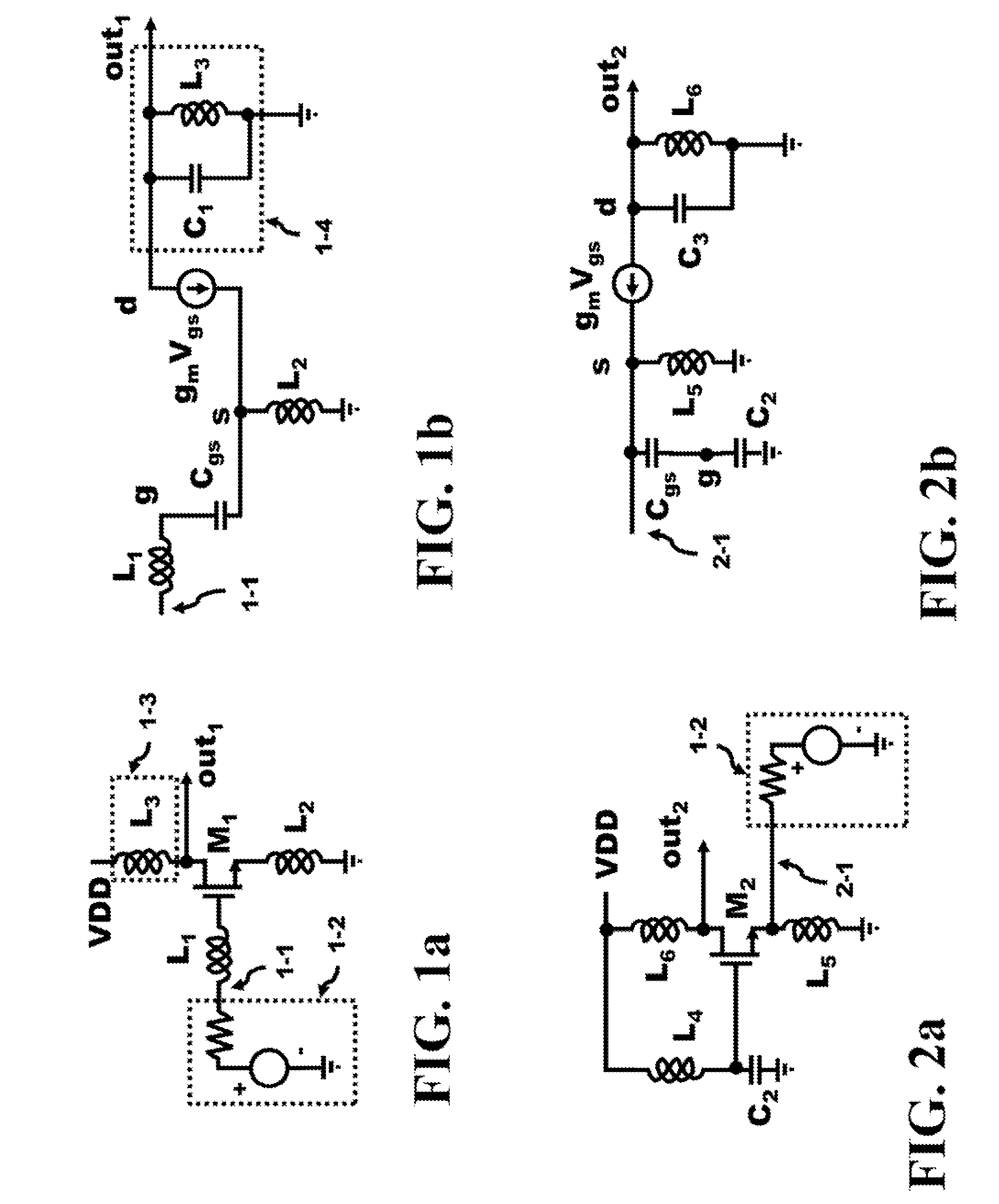
[0036]The inventions presented in this specification can be used in various high frequency system designs. Some of the basic circuits for an analog amplifier include the common source and common gate structures as illustrated in FIG. 1a and FIG. 2a, respectively. The common source configuration of a LNA (Low Noise Amplifier) in FIG. 1a illustrates a voltage source 1-2, a voltage in series with a resistor, that can represent the output of an antenna or another source of an extracted signals. The output 1-1 of the voltage source 1-2 couples to the input of the gate of M1 by the gate inductance L1. The voltage source 1-2 provides the input frequency spectrum to the receiver. The source of M1 is coupled to ground by the inductor L2. At DC, the impedance of the inductor L2 is zero causing the source of M1 to be coupled to ground (GRD or VSS). This configuration is known as the common source. The drain of device M1 is coupled to VDD by a load 1-3, in this case, the inductor L3 and the out...


PUM


Abstract

A cascode common source and common gate LNAs operating at 60 GHz are introduced and described. The cascode common source LNA is simulated to arrive at an optimum ratio of upper device width to the lower device width. The voltage output of the cascode common source LNA is translated into a current to feed and apply energy to the mixer stage. These input current signals apply the energy associated with the current directly into the switched capacitors in the mixer to minimize the overall power dissipation of the system. The LNA is capacitively coupled to the mixer switches in the I and Q mixers and are enabled and disabled by the clocks generated by the quadrature oscillator. These signals are then amplified by a differential amplifier to generate the sum and difference frequency spectra.

Description

CROSS REFERENCE TO RELATED APPLICATIONS[0001]The present application is related to the co-filed U.S. application entitled “An Injection Locked Divider with Injection Point Located at a Tapped Inductor” both filed on Dec. 6, 2011, which are invented by the same inventor as the present application and incorporated herein by reference in their entireties.BACKGROUND OF THE INVENTION[0002]The Federal Communications Commission (FCC) has allotted a spectrum of bandwidth in the 60 GHz frequency range (57 to 64 GHz). The Wireless Gigabit Alliance (WiGig) is targeting the standardization of this frequency band that will support data transmission rates up to 7 Gbps. Integrated circuits, formed in semiconductor die, offer high frequency operation in this millimeter wavelength range of frequencies. Some of these integrated circuits utilize Complementary Metal Oxide Semiconductor (CMOS), Silicon-Germanium (SiGe) or GaAs (Gallium Arsenide) technology to form the dice in these designs. At 60 GHz, t...

Claims


Application Information

Patent Timeline
Patent Type & Authority Applications(United States)
IPC IPC(8): H04B1/16
CPCH03D7/125H03D7/1441H03D7/1466H03D7/165H03F1/223H03F3/387H03F2200/108H03F2200/294H03F2200/492H03F2200/72H03F3/193H03F1/42H03F3/45179H03F2200/451H03F3/45071H03F2200/75H04L27/38
Inventor SOE, ZAW
Owner TENSORCOM
Why Eureka
Try Eureka