Digital phase locked loop device and method in wireless communication system

a wireless communication system and phase lock technology, applied in pulse automatic control, climate sustainability, high-level techniques, etc., can solve the problems of high cost of divider circuits, high cost of manufacturing and manufacturing, and large time taken in manufacturing and manufacturing, so as to reduce the area occupied by pll and power consumption

Active Publication Date: 2013-06-13
SAMSUNG ELECTRONICS CO LTD +1
View PDF7 Cites 25 Cited by
  • Summary
  • Abstract
  • Description
  • Claims
  • Application Information

AI Technical Summary

Benefits of technology

[0007]Another aspect of the present invention is to provide an apparatus and a method for implementing a digital PLL showing high performance at low power and a small area in a wireless communication system.
[0009]A digital PLL according to the present invention may reduce an area occupied by the PLL and power consumption. Accordingly, a high performance digital PLL may be applied to a small sized communication apparatus such as a portable terminal as well as the general communication apparatus.

Problems solved by technology

Also, since an analog signal level is important, a plurality of buffers such as a Voltage-Controlled Oscillator (VCO) buffer, a Local Oscillator (LO) buffer, an Output buffer, etc. are used, so that current consumption becomes very large.
Furthermore, since an analog PLL is sensitive to a process characteristic, almost all blocks should be redesigned when a process changes or is scaled down, so that much time is taken in manufacturing and manufacturing costs increase.
Accordingly, a divider circuit is complicated and power consumption and an area increase.

Method used


Image

  • Digital phase locked loop device and method in wireless communication system
  • Digital phase locked loop device and method in wireless communication system
  • Digital phase locked loop device and method in wireless communication system

Examples


Embodiment Construction

[0024]FIGS. 1 through 11, discussed below, and the various embodiments used to describe the principles of the present disclosure in this patent document are by way of illustration only and should not be construed in any way to limit the scope of the disclosure. Those skilled in the art will understand that the principles of the present disclosure may be implemented in any suitably arranged wireless communications system

[0025]Hereinafter, a preferred embodiment of the present invention is described in detail with reference to the accompanying drawings. Also, descriptions of well-known functions and constructions are omitted for clarity and conciseness.

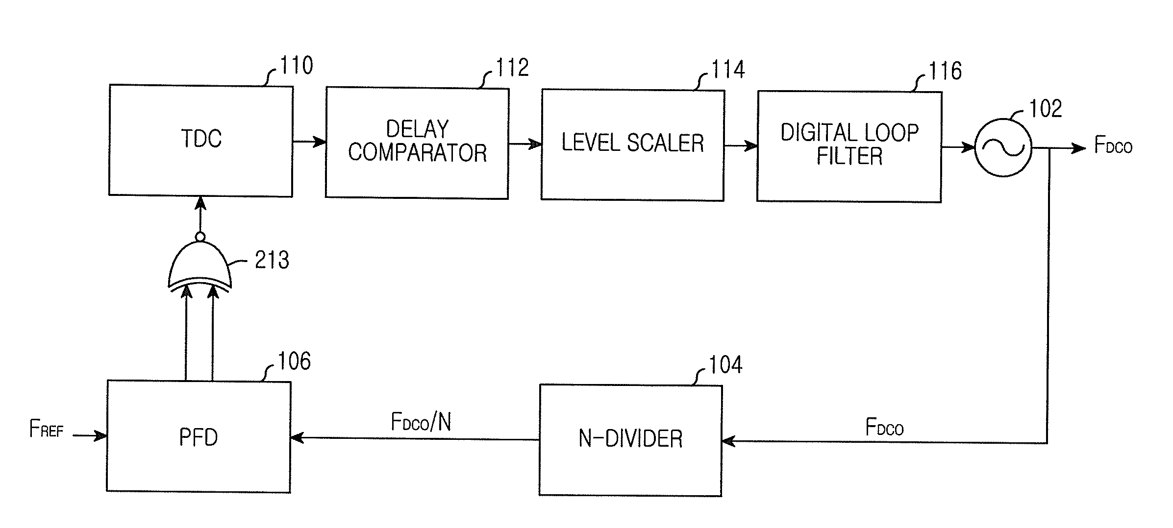
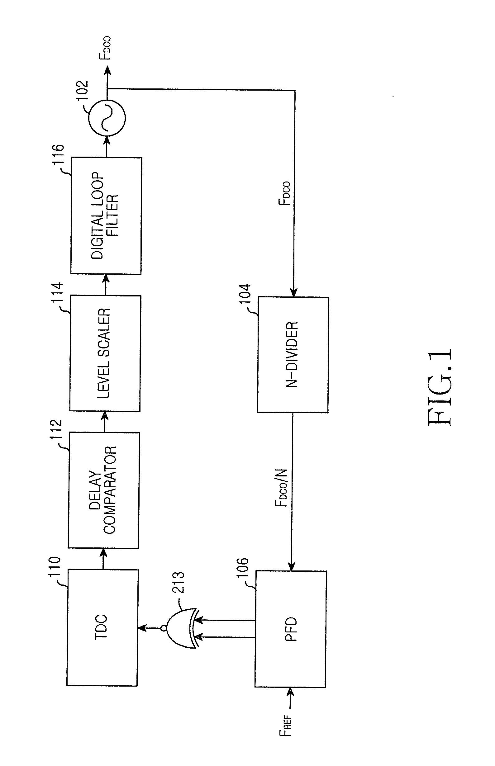
[0026]FIG. 1 is a block diagram illustrating a digital PLL according to an embodiment of the present invention.

[0027]As illustrated in FIG. 1, the digital PLL includes a Digitally Controlled Oscillator (DCO) 102, an N-divider 104, a Phase Frequency Detector (PFD) 106, an eXclusive OR (XOR) operator 108, a Time to Digital Converter (TDC)...


PUM


Abstract

A digital Phase Locked Loop (PLL) in a wireless communication system is provided. The PLL includes a Digitally Controlled Oscillator (DCO), a divider, a Phase Frequency Detector (PFD), a Time to Digital Converter (TDC), a delay comparator, and a level scaler. The DCO generates a frequency signal depending on an input Digital Tuning Word (DTW). The divider divides the frequency signal at an integer ratio. The PFD generates a signal representing a phase difference between a divided frequency signal and a reference signal. The TDC measures a time interval of the phase difference using the signal representing the phase difference. The delay comparator calculates a time interval in the case where rising edges coincide from values measured by the TDC. The level scaler generates a DTW that operates the DCO using a digital code representing the time interval.

Description

BACKGROUND OF THE INVENTION[0001]1. Field of the Invention[0002]The present invention relates to a wireless communication system. More particularly, the present invention relates to a Phase Locked Loop (PLL) digitally implemented in a wireless communication system.[0003]2. Description of the Related Art[0004]A PLL is widely used to generate a carrier of an application in a 4-th Generation (4G) system such as a Long Term Evolution (LTE), a cellular phone such as Bluetooth, a Global Positioning System (GPS), a Wideband Code Division Multiple Access (WCDMA), and a wireless Local Area Network (LAN) such as 802.11a / b / g.[0005]In the conventional analog PLL, since a divider should operate in high speed and includes a current source and cannot use a Width-to-Length (W / L) ratio of Metal Oxide Semiconductor (MOS) minimally depending on a noise and accuracy issue, an area cannot reduce remarkably when a process is scaled down. Since a loop filter includes a passive resistor and a capacitor, it...

Claims


Application Information

Patent Timeline
Patent Type & Authority Applications(United States)
IPC IPC(8): H03L7/089
CPCH03L7/085H03L2207/50Y02B60/50H03L7/18H03L7/089H03L7/0991Y02D30/70
Inventor LEE, KANG-YOONPU, YOUNG-GUNPARK, AN-SOOPARK, JOON-SUNGLEE, JAE-SUP
Owner SAMSUNG ELECTRONICS CO LTD
Why Eureka
Try Eureka