Method for jointing metal member and resin and jointed body thereof

a metal member and resin technology, applied in the direction of superimposed coating process, coating, conductor, etc., can solve the problems of insufficient adhesiveness to the resin, corrosion resistance, heat resistance, solvent resistance, especially corrosion resistance, etc., and achieve the effect of improving the adhesiveness between the metal member and the resin

Inactive Publication Date: 2013-06-27
HITACHI LTD
View PDF3 Cites 1 Cited by
  • Summary
  • Abstract
  • Description
  • Claims
  • Application Information

AI Technical Summary

Benefits of technology

[0022]Obviously, use of methods (1) and (2) at the same time, that is, formation of both the oxide layer and the chelating agent layer for effectively forming the silane coupling agent layer on the surface of the metal member is also effective.
[0023]According to the present invention, adhesiveness between the metal member and the resin can be improved by forming the silane coupling agent layer after forming the oxide layer or the chelating agent layer on the metal member, and a technique and a product having no detachment and cracks between the metal substrate and the resin in a jointed material of the metal member and the resin or the product using the jointed material can be provided.

Problems solved by technology

These materials are easy to be affected by oxidation or contamination, and as a result, sufficient adhesiveness to the resin cannot be obtained.
However, satisfied results in corrosion resistance, heat resistance, and solvent resistance, particularly the corrosion resistance, is not obtained.
In addition, an organic functional silane is not adhered well on the surface of the metal.
Consequently, this treatment is inefficient in terms of energy, and needs a lot of time.
Therefore, this treatment has many problems for practical use.
In a method described in Patent Document 10, although a certain effect of prevention of cracks of a copper type package, its cost becomes huge.
In the method described in Patent Document 11, adhesiveness is not fully improved due to a residual surface oxide film even when the surface is roughened.

Method used


Image

  • Method for jointing metal member and resin and jointed body thereof
  • Method for jointing metal member and resin and jointed body thereof
  • Method for jointing metal member and resin and jointed body thereof

Examples


examples 1 to 11

[0083]Examples 1 to 6 are the cases where the method of [1]-(1) in which the silane coupling agent and the oxidizing agent coexist was applied to metal members to which a copper substrate was plated with Ni. Investigated results of adhesiveness to the resin are shown in Table 2. A concentration of the silane coupling was 1.0% by weight, and ethanol was used as a solvent. A concentration of aqueous hydrogen peroxide solution used as the oxidizing agent was set to 10% by using 30% aqueous hydrogen peroxide solution. Every sample was treated with heat at 100° C. for 1 hour after immersing into the silane coupling agent solution. The oxidizing agent used was hydrogen peroxide. Various silane coupling agents were used to perform the one-step treatment. Adhesiveness strengths to the resin are determined as good in every case. As can be seen from comparison between Comparative example 3 and Example 4, the adhesiveness forces were dramatically improved.

[0084]Examples 7 to 11 are the cases w...

examples 12 to 19

[0086]Investigated result with regard to the method of [1]-(2) in which the metal members are immersed into the silane coupling agent solution after applying oxidation treatment are shown in Table 3. Basically, metal members in which Cu or Ni alloy is used as a substrate and Ni plating or Ni—Sn plating are applied thereto are used. Every sample was treated with heat at 100° C. for 1 hour after immersing into the silane coupling agent solution. A concentration of the silane coupling agent was 1.0% by weight, and ethanol was used as a solvent. Examples 12 to 14 are the cases where the metal member is immersed into the aqueous hydrogen peroxide solution for oxidation treatment being the first-step treatment in the two-step treatment and then immersed into the silane coupling agent solution as the second-step treatment.

[0087]A 10% concentration the aqueous hydrogen peroxide solution was prepared from 30% aqueous hydrogen peroxide solution, and ethanol was used as a solvent. In every Exa...

examples 20 to 26

[0090]Investigated result with regard to the method of [2]-(2) in which the metal members were immersing into the silane coupling agent solution after applying chelating agent treatment are shown in Table 3. Basically, metal members in which Cu was used and Ni plating was applied thereto were used. Every sample was treated with heat at 100° C. for 1 hour after immersing into the silane coupling agent solution. A concentration of the silane coupling was 1.0% by weight, and ethanol was used as a solvent.

[0091]Examples 20 to 24 are the cases where EDTA-2Na was used as the chelating agent in the first step and various silane coupling agent were used. The reason why 2Na salt was used is to increase solubility of the chelating agent to water. A concentration of the chelating agent solution was 2%, and water was used as a solvent. In every Example, high adhesiveness strengths to the resin were obtained. Example 25 is the case where the chelating agent and the oxidizing agent (hydrogen pero...


PUM

PropertyMeasurementUnit
pHaaaaaaaaaa
pHaaaaaaaaaa
temperatureaaaaaaaaaa

Abstract

Reliability is improved by improving adhesiveness, crack resistance, and moisture resistance of a metal member-resin jointed body by enhancing adhesiveness between the metal member and the resin.
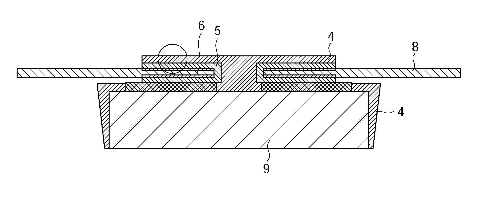
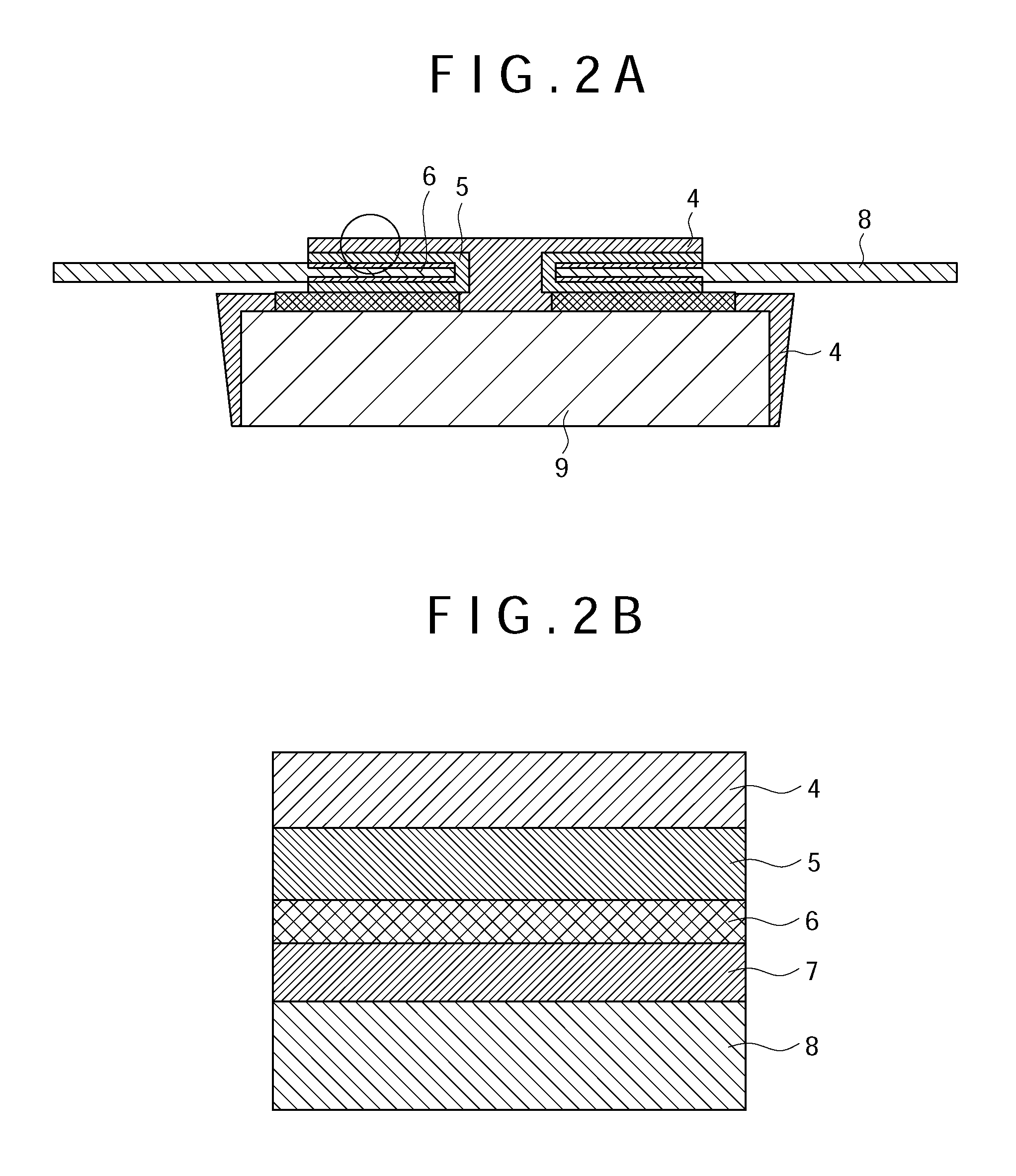
A jointed body of a metal member and a resin including: an intermediate layer and a silane coupling agent layer formed on the metal member at an interface between the metal member and the resin, wherein the silane coupling agent layer and the resin are contacted; the intermediate layer is any one of an oxide layer of the metal, a chelating agent layer, a composite layer made of the oxide layer and the chelating agent layer, and a mixed layer made of the oxide and the chelating agent; and the intermediate layer has an electrically non-insulating characteristic, and a method of manufacturing the same.

Description

FIELD OF THE INVENTION[0001]The present invention relates to a method for adhering which improves adhesiveness force in joint of a metal member and a resin and a jointed body thereof. For example, a lead frame of a semiconductor package is included as an application field. In other words, the present invention relates to a method for manufacturing a lead frame, and particularly, relates to a plated copper lead frame used for a semiconductor device to which a mold package represented by an LOC structure is applied, and a method for manufacturing the same. Other than the above application, for example, the present invention relates to a metal plate covered with a resin film. More specifically, in order to improve adhesion between a metal member and a resin such as an epoxy resin adhesive or a silicone resin adhesive, adhesiveness with an adhesive is improved by applying oxidation treatment or a chelating agent treatment to the surface of a metal member and effectively forming an organ...

Claims


Application Information

Patent Timeline
Patent Type & Authority Applications(United States)
IPC IPC(8): H01L23/00H01B1/00H01L23/495
CPCH01L24/80H01L23/49582H01L2924/15747H01L23/49586H01L23/49572H01L23/49562H01L23/3142H01L23/3107H01L2224/73265H01L2224/48247H01L2224/48091H01B1/00H01L2224/49113H01L2924/00014H01L24/32H01L24/48H01L24/73H01L2924/10253H01L2224/32245H01L2224/45099H01L2924/00012H01L2924/00H01L2924/181H01L24/49
Inventor MABUCHI, KATSUMIAKAHOSHI, HARUOMOTOWAKI, SHIGEHISA
Owner HITACHI LTD
Why Eureka
Try Eureka