Process of preparing graphene by low-frequency electromagnetic wave

a low-frequency electromagnetic wave and graphene technology, applied in the direction of superimposed coating process, coating, material nanotechnology, etc., can solve the problems of difficult to achieve rapid cooling rate, unnecessary energy consumption, and removal of a large amount of thermal energy, and achieve easy control of processing temperature, short processing time, and low energy consumption

Inactive Publication Date: 2013-08-08
NATIONAL TSING HUA UNIVERSITY
View PDF6 Cites 18 Cited by
  • Summary
  • Abstract
  • Description
  • Claims
  • Application Information

AI Technical Summary

Benefits of technology

[0009]An object of the present invention is to provide a graphene production method. This method has advantages including short processing time, low energy consumption, and easy-to-control processing temperature, and can be promising alternative to conventional chemical vapor deposition method for producing graphene. In addition, the method of the present invention can also offer possibility for large production of graphene in a cost-effective way.
[0012]Generally, a major media for forming a microwave field is electromagnetic wave, therefore, transfer of electromagnetic energy to a target could be rapid. Further, the microwave field can be controlled within a specific space without covering other materials, thus directly heats a target to achieve an ideal temperature. In addition, because it is unnecessary to heat the device directly, unnecessary energy consumption could therefore be decreased. As a result, in comparison with the conventional high temperature furnace tubes, there would be no need to consider equipment in the microwave production process, therefore the total heat capacity is far smaller than conventional high temperature furnace tubes heating system.
[0013]In addition, as described above, the whole system can change temperatures quickly because the total heat capacity requirement to increase the temperature is small. The conventional high temperature furnace tubes heating system is unable to directly control cooling process and thermal energy is largely retained in the system that cannot be removed, instead, in the microwave system, thermal energy is dissipated rapidly as soon as the microwave supplier is turned off and when the microwave field collapses. Furthermore, the microwave's output power can be changed to meet a required temperature curve. As a result, the present invention of graphene production method can achieve the requirement of short process time, low energy consumption, and easy-to-control processing temperature.
[0018]In the present invention of graphene production method, a carbon-containing layer on the metal substrate in the step (C) is formed by evaporation, sputtering, or coating, where sputtering is preferred. Carbon sources in the step (C) may be ordered carbon or carbon-based polymer, such as polymethylmethacrylate (PMMA), polydimethylsiloxane (PDMS), polycarbonate (PC), or polyethylene terephthalate (PET), etc, for which a solid state, liquid state, or gas state of carbon source can all be used. Furthermore, the thickness of the carbon-containing layer may be 5 nm to 100 nm, where 5 nm to 20 nm is preferred. The thickness layer thinner than 5 nm has poor continuation of formed carbon films and may not obtain continuous thin films in large area, however, when the thickness of the carbon-containing layer is more than 100 nm, there is too much carbon and can make it difficult for the carbon films to be fused into metal layer, and the remaining part of it will remain on the surface to form protrusions Further, because the carbon-containing layer in the system is solid, it is much more easier to control the process without worrying about vortex effect caused by fluid mechanics hydrodynamics.
[0021]In another aspect of the present invention of the graphene production method, there further comprises a step (E) after the step (D), for turning off the microwave field device for cooling and turning on the microwave field device again, wherein the step (E) is repeated more times to form multiple graphene layers. By warming and cooling the system via turning on / off the microwave device described above to grow graphene layer by layer, a high quality and large-area graphene could be obtained, therefore reducing occurrence of degraded graphene products, and producing graphene layers based on a practical application of requirement. In addition, in the present invention of graphene production method, the backward graphene's thickness may be 2 nm to 50 nm, and the forward graphene's thickness may be 1 nm to 5 nm, both of the two graphene layers may change layer numbers by adjusting parameters, however, there is no limitation on the layer numbers in the present invention.

Problems solved by technology

However, the methods described above have some drawbacks, for example, (1) the high temperature furnace tube used in CVD cannot withstand rapid temperature changes, which may cause a limitation on the whole procedure of heating and cooling process, resulting in long manufacturing process; (2) high consumption rate, the whole system is susceptible to heating while the furnace tubes are heating products, such operation could lead to unnecessary energy consumption; (3) difficulty in carbon source control, the CVD method works to get its carbon source from gasses such as methane or ethylene, which then undergoes high temperature pyrolysis to derive carbon atoms, but there is a good possibility for the gases to form vortexes of different sizes in different locations, this could increase unprocessibility in the manufacturing processes; (4) difficulty in cooling rate control, since the entire system is subject to heating, a great deal of thermal energy is stored due to the large heat capacitance of the system, this could lead to a requirement for removal of a great amount of thermal energy during the cooling process, and this could mean difficulty in attempting to achieve rapid cooling rate; and (5) low temperature maneuverability, due to the high storage of thermal energy inside the system, changing system's temperature would not be an easy task to handle, and could mean difficulty in handling the system using complex temperature curves.
In view of the above, the aforementioned drawbacks could present to be obstacles to mass production for industrial graphene.

Method used


Image

  • Process of preparing graphene by low-frequency electromagnetic wave
  • Process of preparing graphene by low-frequency electromagnetic wave
  • Process of preparing graphene by low-frequency electromagnetic wave

Examples


embodiment 1

Preparation of Graphene Layers

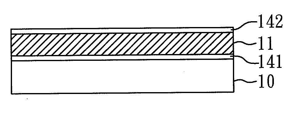
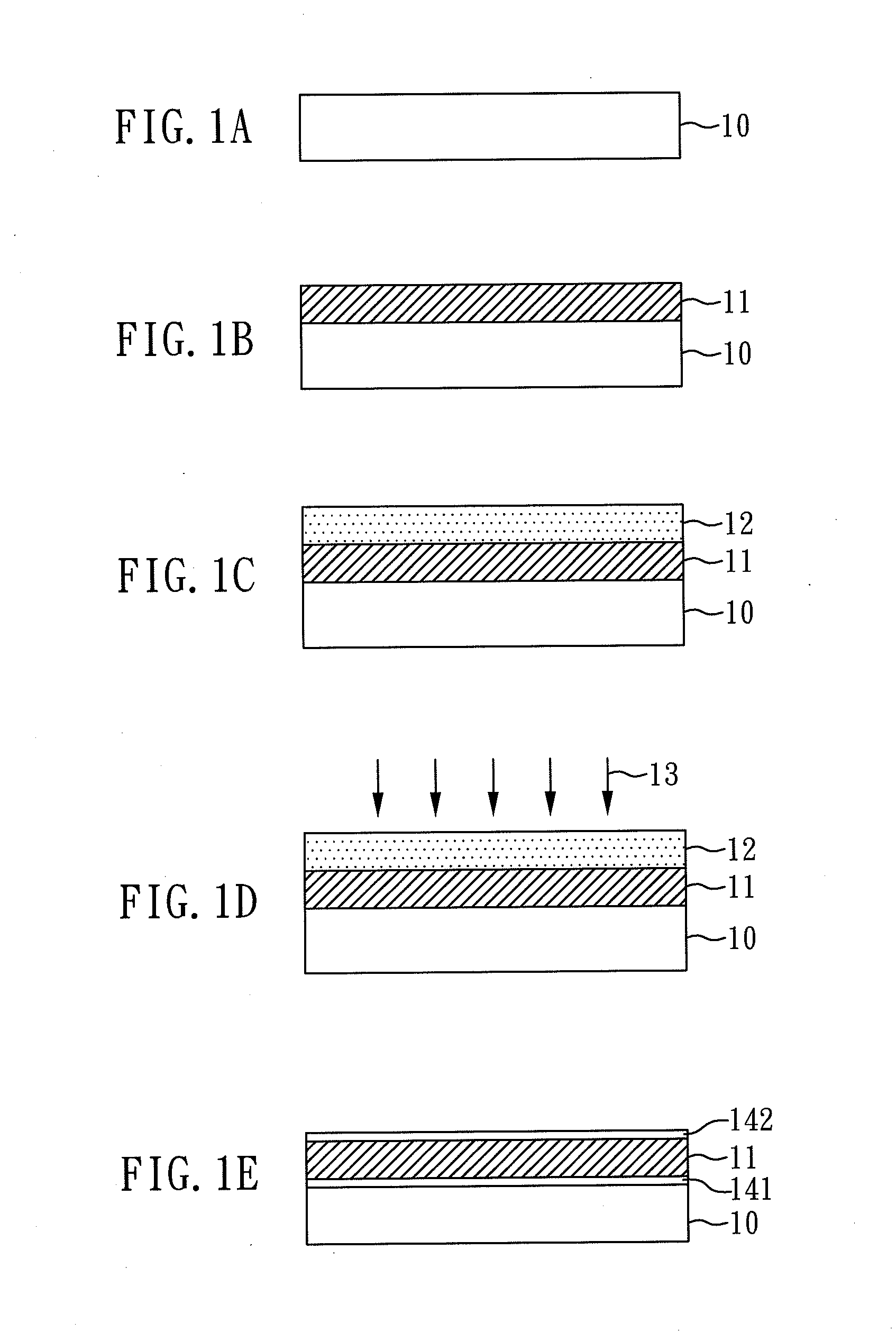
[0032]First, referring to FIG. 1A, there is provided a substrate 10, and then a metal layer 11 is evaporated onto the substrate 10 (see FIG. 1B), wherein the substrate 10 is made of silicon oxide and the metal layer 11 is made of nickel which has a thickness of 50 nm in this embodiment. In addition, the conditions of a metal layer-forming evaporation procedure, comprising: 5×10⁻⁶ torr degree of vacuum, and the evaporation rate is 0.3-1 Å / s.

[0033]Next, referring now to FIG. 1C, a carbon-containing layer 12 is formed on the metal layer 11. In this embodiment, a disordered carbon is used as carbon source, and then deposited by electron beam evaporation method to form the carbon-containing layer 12 on the metal layer 11, and the carbon-containing layer 12 has a thickness about 20 nm. Further, the conditions of the carbon-containing layer procedure, comprising: 5×10⁻⁶ torr degree of vacuum, and the evaporation rate is 0.3-1 Å / s. Now the silicon oxide substra...


PUM

PropertyMeasurementUnit
thicknessaaaaaaaaaa
thicknessaaaaaaaaaa
frequencyaaaaaaaaaa

Abstract

The present invention relates to a process of inducing grapheme by low-frequency electromagnetic wave, which includes the following steps: (A) providing a substrate; (B) optionally forming a metal layer on the substrate; (C) providing a carbon source to form a carbon-containing layer locating on the metal layer; and (D) performing a treatment of the carbon-containing layer formed on the metal layer by using low-frequency electromagnetic wave, wherein the low-frequency electromagnetic wave is provided by microwave device. The electromagnetic energy from the microwave field device is converted to thermal energy by microwave absorber (for example, SiC) as a media to directly heat the carbon-containing layer, so that carbon atoms get kinetic energy to form grapheme layers on the surface of the metal layer and between the metal layer and the substrate.

Description

CROSS REFERENCE TO RELATED APPLICATION[0001]This application claims the benefits of the Taiwan Patent Application Serial Number 101104065, filed on Feb. 8, 2012, the subject matter of which is incorporated herein by reference.BACKGROUND OF THE INVENTION[0002]1. Field of the Invention[0003]The present invention relates to a process of producing graphene, and more particularly, to produce graphene by low-frequency electromagnetic wave.[0004]2. Description of Related Art[0005]Graphene is a two-dimensional material formed by carbon atoms. Those sp2-bonded carbon-atoms are linked into six-membered rings, which extends into a two-dimensional planar. Due to the unique two-dimensional structure, carrier such as electrons or holes in graphene can transport at an extremely high speed to make excellent electrical and thermal conduction. Moreover, because the bonding between carbon atoms is extremely strong, as a result graphene has excellent mechanical properties that can be applied to be used...

Claims


Application Information

Patent Timeline
Patent Type & Authority Applications(United States)
IPC IPC(8): C01B31/04
CPCC01B31/0446B82Y30/00B82Y40/00Y10S977/844C01B32/184
Inventor CHUEH, YU-LUNYEN, WEN-CHUNLIN, HUNG-CHIAO
Owner NATIONAL TSING HUA UNIVERSITY
Why Eureka
Try Eureka