
System and method for reducing halogen levels necessary for mercury control, increasing the service life and/or catalytic activity of an scr catalyst and/or control of multiple emissions

a technology of scr catalyst and halogen level, applied in the direction of emission prevention, combustion type, separation process, etc., can solve the problems of ammonia level, precious metal catalyst less attractive, and its potential to oxidize, so as to reduce or prevent the poisoning and/or contamination of scr catalyst, and reduce the level of one or more halogens

Active Publication Date: 2013-12-19
THE BABCOCK & WILCOX CO
View PDF3 Cites 14 Cited by
  • Summary
  • Abstract
  • Description
  • Claims
  • Application Information

AI Technical Summary

Benefits of technology

The present invention provides a method and apparatus for reducing the levels of halogens, phosphorus, and other emissions from combustion devices such as boilers, heaters, and kilns. The invention involves the use of metal-bearing compounds that react with the halogens, phosphorus, and other compounds to form less harmful compounds. The invention can be used to control mercury levels, protect catalysts, and control various emissions. The method includes providing halogen-containing compounds to a combustion device, providing metal-bearing compounds at both before and after the point of conversion of the halogens, and permitting the metal-bearing compounds to catalyze the conversion of the halogens to elemental halogens which then react with gaseous mercury to form mercury halides. The invention also includes a method for reducing gaseous acid compounds and phosphorus compounds in flue gas and syngas production processes, respectively. Overall, the invention provides a way to reduce harmful emissions and improve air quality.

Problems solved by technology

Rather, it is a practical limit set to prevent excessive levels of ammonia slip.
The major drawback of the base metal catalyst is its potential to oxidize SO2 to SO3; the degree of oxidation varies based on catalyst chemical formulation.
However, SO2 oxidation to SO3 and high material costs often make precious metal catalysts less attractive.
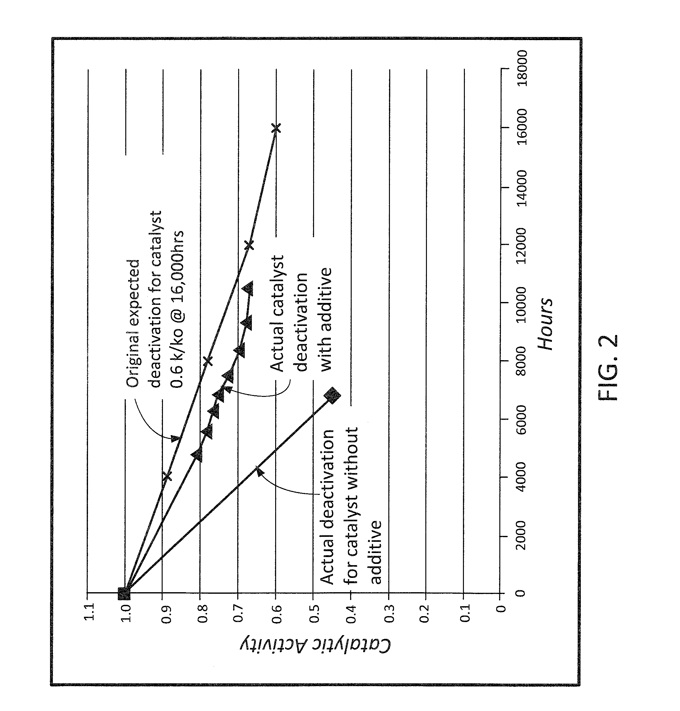
Additionally, it is also well known that SCR catalysts degrade over time and have to be replaced periodically at a significant cost and loss of generating capacity.
More particularly, as the SCR catalysts are exposed to the dust laden flue gas there are numerous mechanisms including blinding, masking and poisoning that deactivates the catalyst and causes a decrease in the catalyst's performance over time.
While this treatment process does an excellent job of removing the desired poisons it produces wastewater with very high arsenic concentrations.
In another situation, Powder River Basin / Lignite coal plants, any coal / biomass co-combustion, or any coal / bone meal co-combustion or even pure biomass combustion power plants will suffer from phosphorus contamination of their SCR catalysts.
It has been found that when mercury control is accomplished in whole, or in part, through the use of one or more halogen compounds (e.g., halide salts such as calcium bromide, etc.) that such compounds negatively impact on the selenium speciation in the flue gas which in turn negatively impacts the amount of selenium that is emitted via the liquid effluent outflow from one or more WFGD units, and or the particulate matter produced by one or more DFGD units that are utilized to control SOx in the same flue gas stream.
Hydrogen halide gases including, but not limited to, HBr gas are not very reactive towards mercury and cause both high temperature corrosion under reducing atmosphere in a furnace and low temperature corrosion at an air heater outlet.
Additionally, other coal-based process such as the production of syngas from coal produce undesirable levels of phosphorus compounds thereby resulting in the undesirable deactivation of one or more catalysts associated with such production processes.

Method used


Image

  • System and method for reducing halogen levels necessary for mercury control, increasing the service life and/or catalytic activity of an scr catalyst and/or control of multiple emissions
  • System and method for reducing halogen levels necessary for mercury control, increasing the service life and/or catalytic activity of an scr catalyst and/or control of multiple emissions

Examples


Embodiment Construction

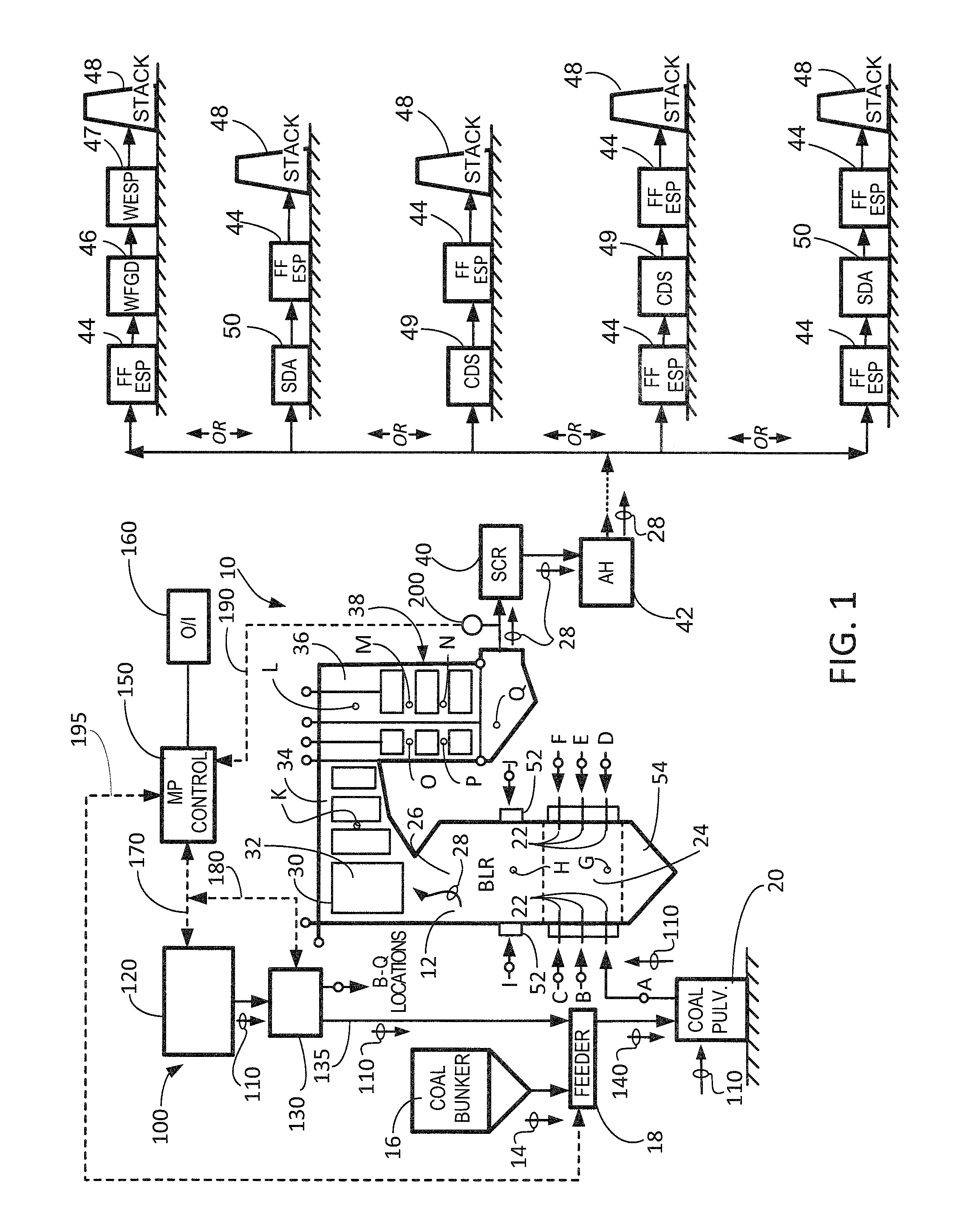
[0028]The present invention relates generally to the field of emission control equipment for boilers, heaters, kilns, or other flue gas-, or combustion gas-, generating devices (e.g., those located at power plants, processing plants, etc.) and, in particular to a new and useful method and apparatus for: (i) reducing halogen levels necessary to affect gas-phase mercury control; (ii) reducing or preventing the poisoning and / or contamination of an SCR catalyst; and / or (iii) controlling various emissions. In another embodiment, the method and apparatus of the present invention is designed to: (a) achieve a reduction in the level of one or more halogens, or halogen-containing compounds, necessary to affect gas-phase mercury control; (ii) achieve protection of, increase the catalytic activity, and / or increase the catalytic life span of an SCR catalyst; and / or (iii) achieve control of various emissions from a combustion process (e.g., control of selenium emissions). In still another embodi...


PUM

PropertyMeasurementUnit
temperatureaaaaaaaaaa
concentrationaaaaaaaaaa

Abstract

The present invention relates generally to the field of emission control equipment for boilers, heaters, kilns, or other flue gas-, or combustion gas-, generating devices (e.g., those located at power plants, processing plants, etc.) and, in particular to a new and useful method and apparatus for: (i) reducing halogen levels necessary to affect gas-phase mercury control; (ii) reducing or preventing the poisoning and / or contamination of an SCR catalyst; and / or (iii) controlling various emissions. In still another embodiment, the present invention relates to a method and apparatus for: (A) simultaneously reducing halogen levels necessary to affect gas-phase mercury control while achieving a reduction in the emission of mercury; and / or (B) reducing the amount of selenium contained in and / or emitted by one or more pieces of emission control equipment for boilers, heaters, kilns, or other flue gas-, or combustion gas-, generating devices (e.g., those located at power plants, processing plants, etc.).

Description

RELATED APPLICATION DATA[0001]This patent application claims priority to and is a continuation-in-part of U.S. patent application Ser. No. 13 / 769,686 filed Feb. 18, 2013 and titled “System and Method for Increasing the Service Life and / or Catalytic Activity of an SCR Catalyst and Control of Multiple Emissions,” which itself claims priority to and is a continuation-in-part of U.S. patent application Ser. No. 13 / 117,332 filed May 27, 2011 and titled “System and Method for Increasing the Service Life and / or Catalytic Activity of an SCR Catalyst and Control of Multiple Emissions,” which itself claims priority to and is a continuation-in-part of U.S. patent application Ser. No. 12 / 691,527 filed Jan. 21, 2010 and titled “System and Method for Protection of SCR Catalyst and Control of Multiple Emissions,” which itself claims priority to and is a non-provisional of U.S. Provisional Patent Application No. 61 / 171,619 filed Apr. 22, 2009 and titled “System and Method for Protection of SCR Cata...

Claims


Application Information

Patent Timeline
Patent Type & Authority Applications(United States)
IPC IPC(8): B01D53/64
CPCB01D53/64B01D53/501B01D53/508B01D53/8631B01D53/869B01D53/8696F23J15/006F23N5/003B01D2251/304B01D2251/306B01D2251/404B01D2251/60B01D2255/20738B01D2257/10B01D2257/55B01D2257/602B01D2258/0283F23C2201/101F23J2215/20F23J2217/101F23J2217/102F23J2219/10F23J2219/40F23J2219/60F23K2201/505B01D2251/108B01D2255/20753B01D2255/20761B01D2255/20792F23J7/00F23J15/003F23J2215/30F23J2215/60B01D53/8659B01D53/46B01J33/00
Inventor GADGIL, MANDAR R.JANKURA, BRYAN J.
Owner THE BABCOCK & WILCOX CO
Learn More