Porous polymer membrane with covalent network structure and production method thereof
- Summary
- Abstract
- Description
- Claims
- Application Information
AI Technical Summary
Benefits of technology
Problems solved by technology
Method used
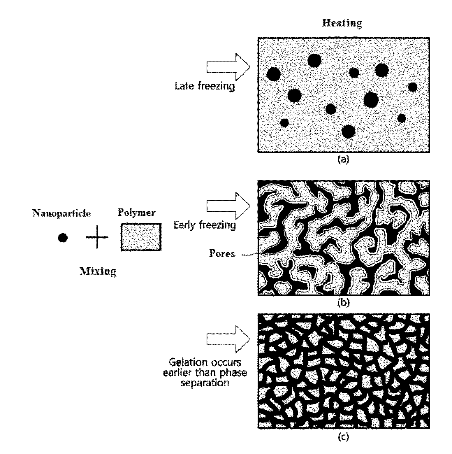
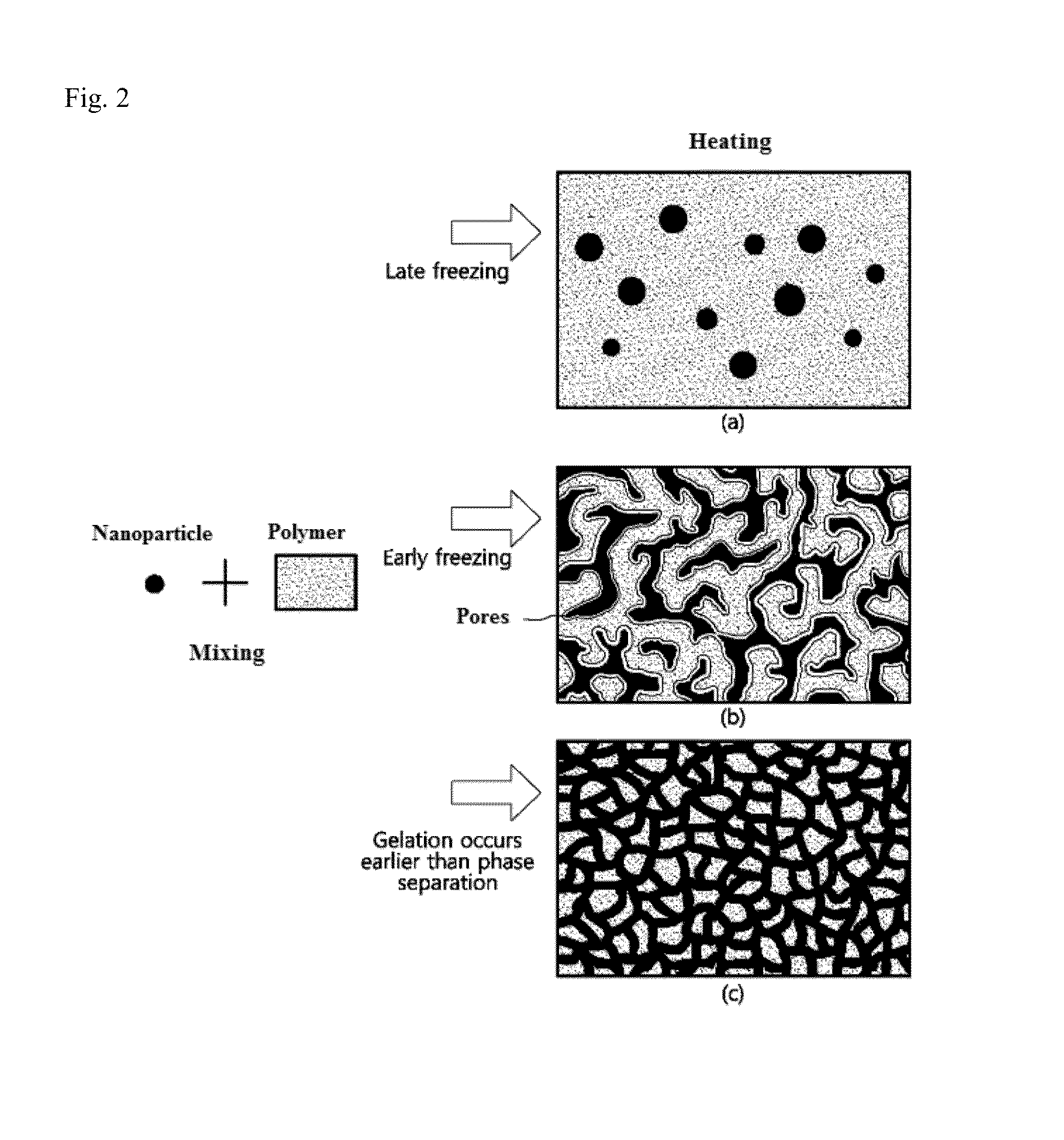
Image

Examples
production example 1
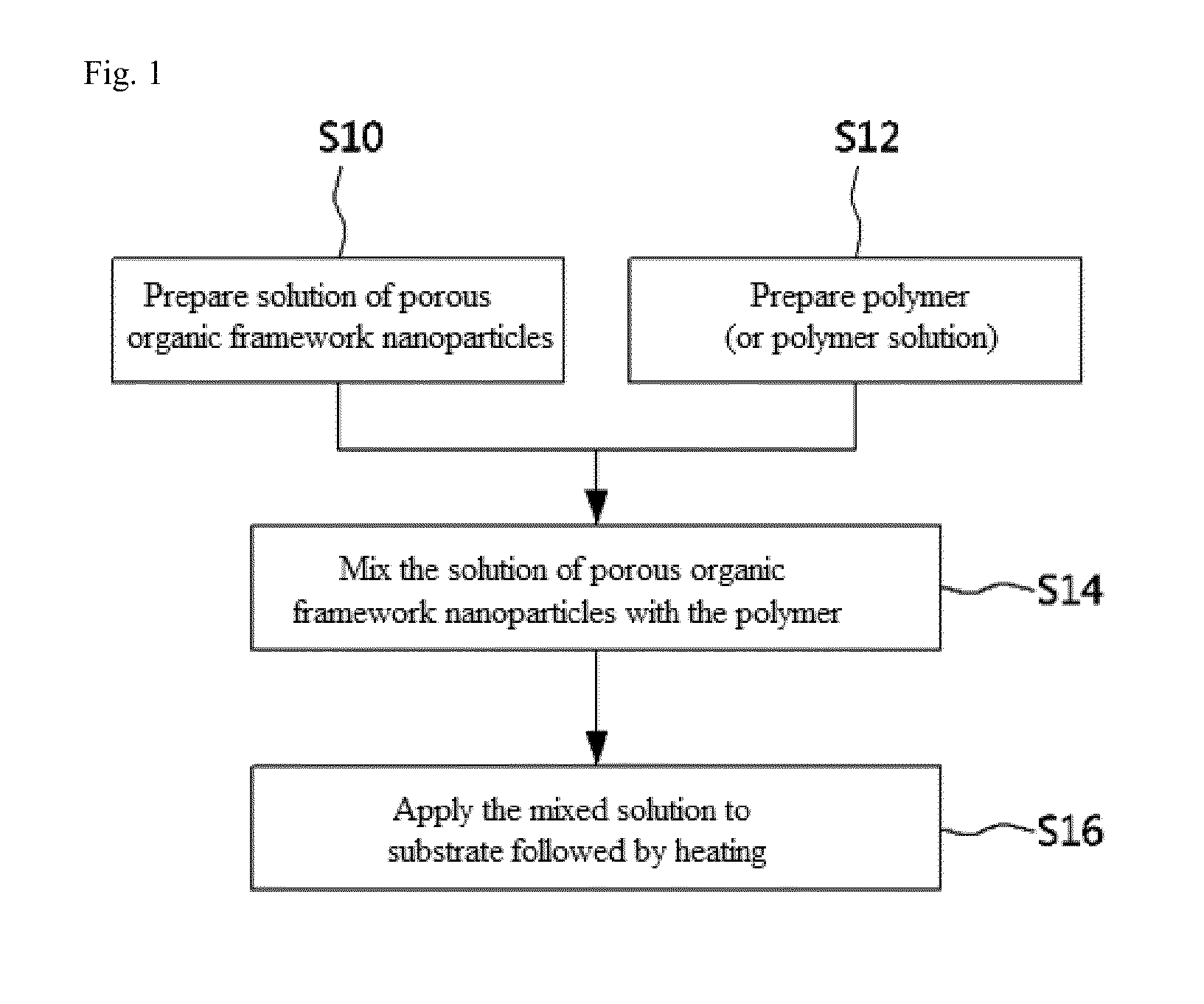
[0087]Preparation of Solution (Sol) of Porous Organic Framework Nanoparticles
[0088]Tetra(4-aminophenyl)methane (Mw=382.50, 0.232 g, 0.607 mmol) was dissolved in N,N-dimethylformide (DMF) to prepare a 4% (w / v) organic solution. 1,6-Diisocyanatohexane (Mw=168.19, 0.204 g 1.214 mmol) was dissolved in DMF to prepare a 4% (w / vol) organic solution. Then, the tetra(4-aminophenyl)methane solution was slowly added to the 1,6-diisocyanatohexane solution to prepare a monomer solution. The monomer solution was allowed to polymerize under a nitrogen atmosphere at room temperature for 62 hr, affording a solution of porous organic framework nanoparticles.
[0089]Production of Porous Polymer Membrane
[0090]The solution of the nanoparticles was mixed with polysulfone as a polymer in such an amount that the nanoparticles were present in an amount of 20 wt % with respect to the total weight of the nanoparticles and the polymer (the same applies below). For stabilization, the mixed solution was stirred at...
production example 2
[0092]A solution of nanoparticles was prepared in the same manner as in Production Example 1. The solution of the nanoparticles was mixed with polysulfone in such an amount that the nanoparticles were present in an amount of 40 wt %. For stabilization, the mixed solution was stirred at 60° C. for 2 hr and at room temperature (25° C.) for 30 min. Subsequently, the stabilized mixed solution was cast on a glass plate and sequentially heated at 50° C., 80° C. and 100° C., each for 2 hr, completing the production of a porous polymer membrane.
[0093]FIG. 5 is a cross-sectional scanning electron microscopy image of the polymer membrane produced in Production Example 2. Referring to FIG. 5, the sol-gel reaction of the nanoparticles from sol to gel occurred earlier than that in Production Example 1 (content of the nanoparticles=20 wt %), leading to aggregation of a smaller number of the nanoparticles, and the polymer membrane had a structure in which the nanoparticles were connected in the fo...
production example 3
[0094]A solution of nanoparticles was prepared in the same manner as in Production Example 1. The solution of the nanoparticles was mixed with polysulfone in such an amount that the nanoparticles were present in an amount of 60 wt %. For stabilization, the mixed solution was stirred at 60° C. for 2 hr and at room temperature (25° C.) for 30 min. Subsequently, the stabilized mixed solution was cast on a glass plate and sequentially heated at 50° C., 80° C. and 100° C., each for 2 hr, completing the production of a porous polymer membrane.
[0095]FIG. 6 is a surface (a) and cross-sectional (b) scanning electron microscopy images of the polymer membrane produced in Production Example 3. Referring to FIG. 6, phase separation was induced by mixing of the polysulfone but gelation of the nanoparticles occurred earlier than that in Production Example 1 (content of the nanoparticles=20 wt %) and that in Production Example 2 (content of the nanoparticles=40 wt %). As a result, a transient struc...
PUM
| Property | Measurement | Unit |
|---|---|---|
| Time | aaaaa | aaaaa |
| Time | aaaaa | aaaaa |
| Shrinkage | aaaaa | aaaaa |
Abstract
Description
Claims
Application Information
 - R&D
- Intellectual Property
- Life Sciences
- Materials
- Tech Scout
- Unparalleled Data Quality
- Higher Quality Content
- 60% Fewer Hallucinations
Browse by: Latest US Patents, China's latest patents, Technical Efficacy Thesaurus, Application Domain, Technology Topic, Popular Technical Reports.
© 2025 PatSnap. All rights reserved.Legal|Privacy policy|Modern Slavery Act Transparency Statement|Sitemap|About US| Contact US: help@patsnap.com