
Carbon as grazing incidence EUV mirror and spectral purity filter

a technology of euv mirrors and carbon, applied in the field of carbon as grazing incidence euv mirrors and spectral purity filters, can solve the problems of imposing a repair cycle, reducing the life of optics, and reducing the service life of optics, so as to overcome or reduce the disadvantages

Inactive Publication Date: 2014-06-19
KLA TENCOR TECH CORP
View PDF0 Cites 7 Cited by
  • Summary
  • Abstract
  • Description
  • Claims
  • Application Information

AI Technical Summary

Benefits of technology

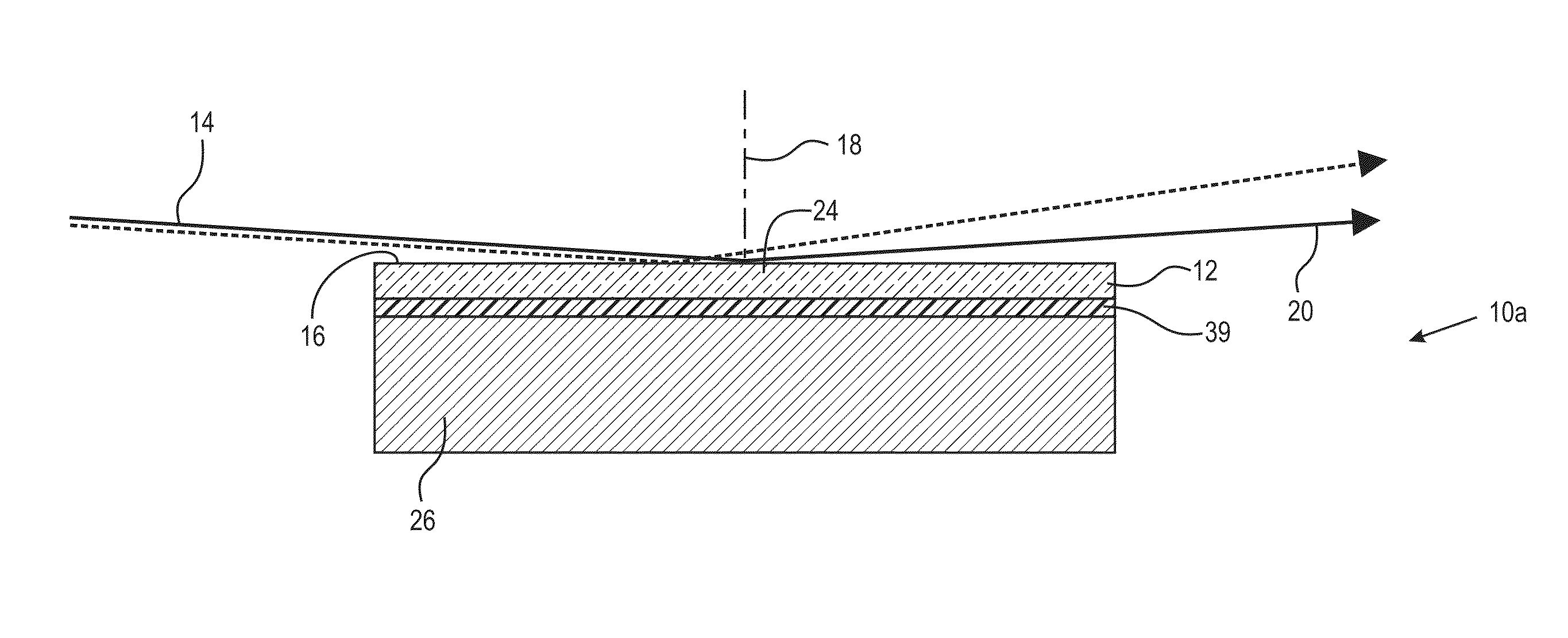
The invention provides a mirror for extreme ultraviolet light (EUV) that has high reflectivity towards curved incident optics while suppressing reflectivity at other spectral regions. The mirror has a long life-time of optics and is compatible with various substrates such as silicon and quartz. It includes a high density carbon film with high reflectivity in EUV and reduced sensitivity to contamination. The invention also offers a solution to reduce or eliminate the use of hydrogen in the system and avoids the issue of metal hydride contamination.

Problems solved by technology

Although old methods have high reflectivity towards EUV, they are susceptible to surface contamination and oxidation by EUV irradiation under vacuum in the presence of residual water, as well as hydrocarbon contamination under EUV irradiation.
The need for oxide removal imposes a repair cycle (impacting tool utilization), shortens optics lifetime, and adds contamination risk from metal hydrides.
Carbon deposits, as a result of Hydrocarbon (HC) contaminants interaction with EUV, are undesirable for both normal and grazing incidence EUV optics, since carbon contamination reduces the inband EUV reflectivity in a non-uniform way.

Method used


Image

  • Carbon as grazing incidence EUV mirror and spectral purity filter
  • Carbon as grazing incidence EUV mirror and spectral purity filter
  • Carbon as grazing incidence EUV mirror and spectral purity filter

Examples


Embodiment Construction

[0019]The following defined terms and definitions assist in understanding the metes and bounds of the invention.

[0020]“HC” means hydrocarbon.

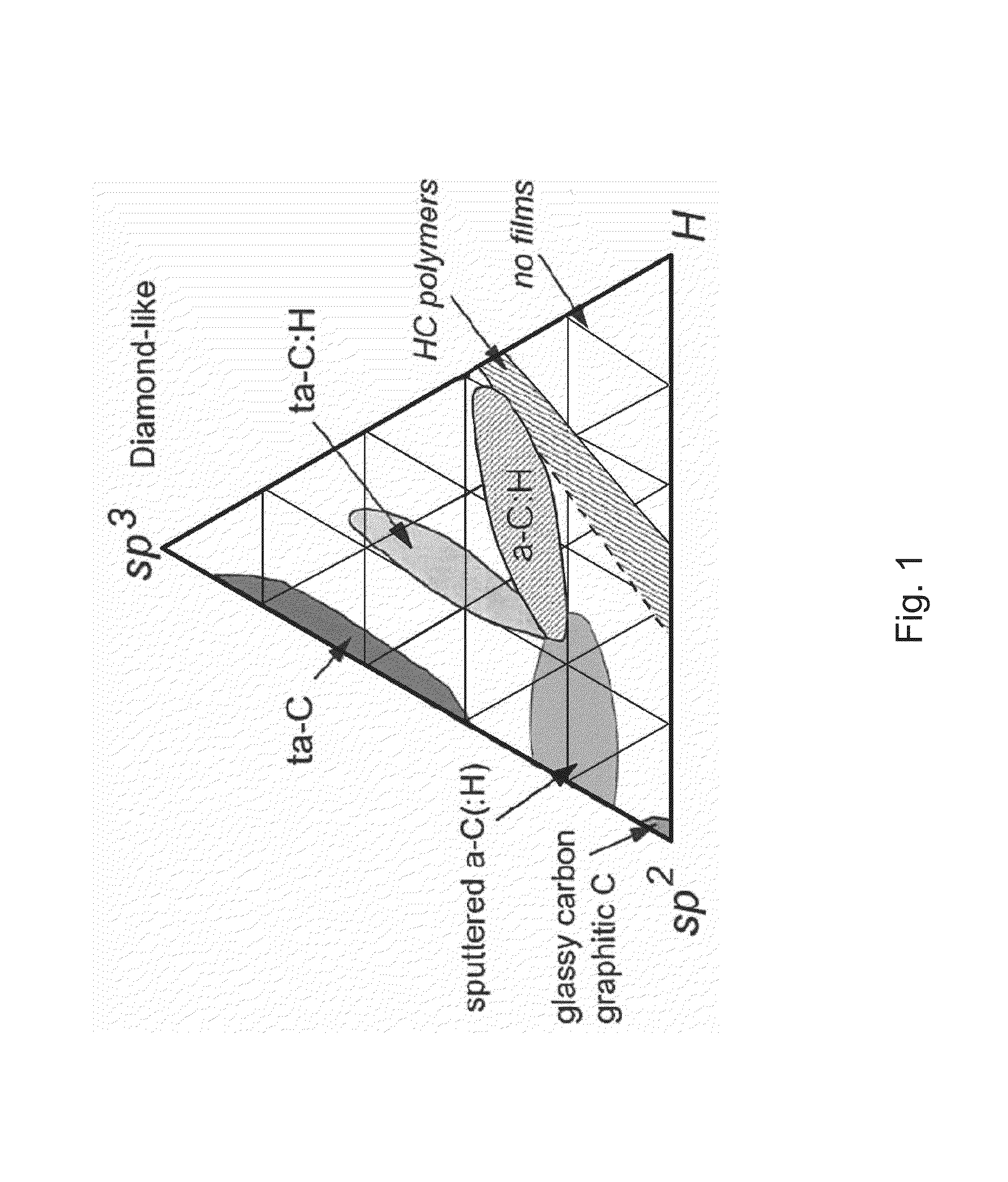
[0021]“High density carbon” is carbon having a specific gravity of at least 2.0 g / cm2 and has an Sp2 / Sp3 ratio of 0 to 3.

[0022]“Hard carbon” is carbon having the hardness of high density carbon but is desirably 40-120 Gpa and most desirably at least 40 Gpa.

[0023]“Ta-C” means a high density hard carbon form having an Sp2 / Sp3 ratio of 0.1 to 1.5 with no more than five percent hydrogen-carbon bond content by stochiometry.

[0024]“Diamond-like carbon”; “DLC” is high density carbon having a ratio of Sp2 / Sp3 carbon-carbon bond of 1.5 to 1.7.

[0025]“UV” radiation, as used herein, means radiation having a wavelength between 3 and 400 nm.

[0026]“DUV” is deep UV radiation (also sometimes referred to as damaging UV radiation) having a wavelength of 22 to 330 nm.

[0027]“NIR” means near infrared radiation, wave length to 0.9 to 2.4 microns.

[0028]“VIS” is visible...


PUM

PropertyMeasurementUnit
grazing angleaaaaaaaaaa
thicknessaaaaaaaaaa
grazing incidence normal angleaaaaaaaaaa

Abstract

A mirror for reflecting extreme ultraviolet light (EUV) comprising: a substrate layer; and an upper layer above the substrate layer, that reflects EUV wavelengths and refracts longer wavelengths, said upper layer being dense and hard carbon having an Sp2 to Sp3 carbon bond ratio of 0 to about 3 and a normal incidence EUV mirror comprising an optical coating on an uppermost surface which permits transmission of EUV and protects the surface from environmental degradation, said coating being dense and hard and having an Sp2 carbon bond ratio of 0 to about 3 and a thickness of 0.1 to about 5 nanometers. The invention also includes EUV mirror systems protected by a dense carbon layer and includes a multilayer EUV reflecting system having an out of band absorbing layer.

Description

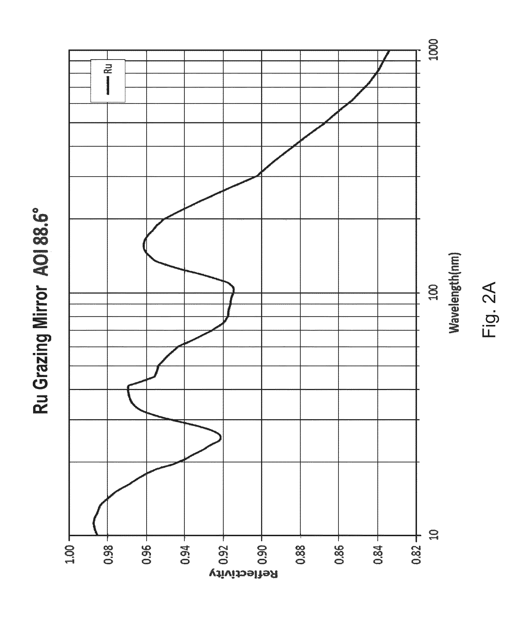
BACKGROUND OF THE INVENTION[0001]This application claims the benefit under 35 U.S.C. §119(e) of U.S. Provisional Application No. 61 / 736,709, filed Dec. 13, 2102.[0002]Among the most widely used grazing incident mirrors for reflecting EUV in-band (λ=13.5 plus or minus 2%) are Ru, Mo and Nb. These materials were also used as an EUV multilayer mirror capping layer.[0003]Although old methods have high reflectivity towards EUV, they are susceptible to surface contamination and oxidation by EUV irradiation under vacuum in the presence of residual water, as well as hydrocarbon contamination under EUV irradiation. The amount of oxide on the grazing incident mirror made of Ru, Mo and Nb, or on the capping layer made of Ru, Mo and Nb, on normal incident multilayer mirrors (ML), need to be very thin, e.g. 2 to 2.5 nanometers. Otherwise, the in-Band EUV reflectivity would decrease, since each of the metal oxide is more absorbing than the non-oxidized metal for in-band EUV. To recover the in-ban...

Claims


Application Information

Patent Timeline
Patent Type & Authority Applications(United States)
IPC IPC(8): G02B5/08
CPCG21K1/062G21K1/067G02B5/0891
Inventor ROSE, GARRYZHUANG, GUORONG VERADELGADO, GILDARDOZHANG, QIANG
Owner KLA TENCOR TECH CORP
Learn More