

Material for organic electroluminescent element, and organic electroluminescent element produced using same
a technology of organic electroluminescent elements and materials, which is applied in the direction of luminescent compositions, organic chemistry, luminescent compositions, etc., can solve the problems of short life, phosphorescent organic el devices, and inability to obtain high-performance devices by simple application of fluorescent device techniques, etc., to achieve high triplet energy state, high triplet energy in emitting layers, and high luminous efficiency
- Summary
- Abstract
- Description
- Claims
- Application Information
AI Technical Summary
Benefits of technology
Problems solved by technology
Method used
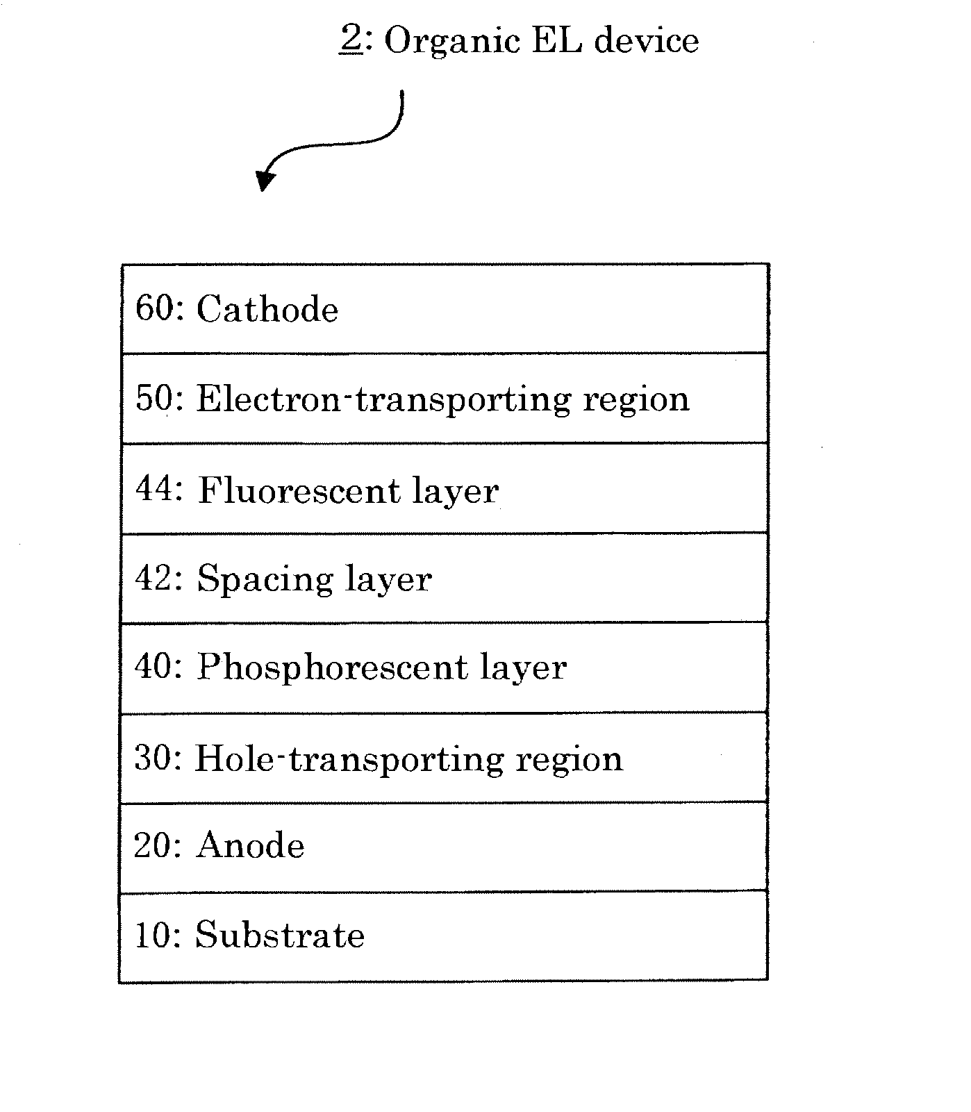
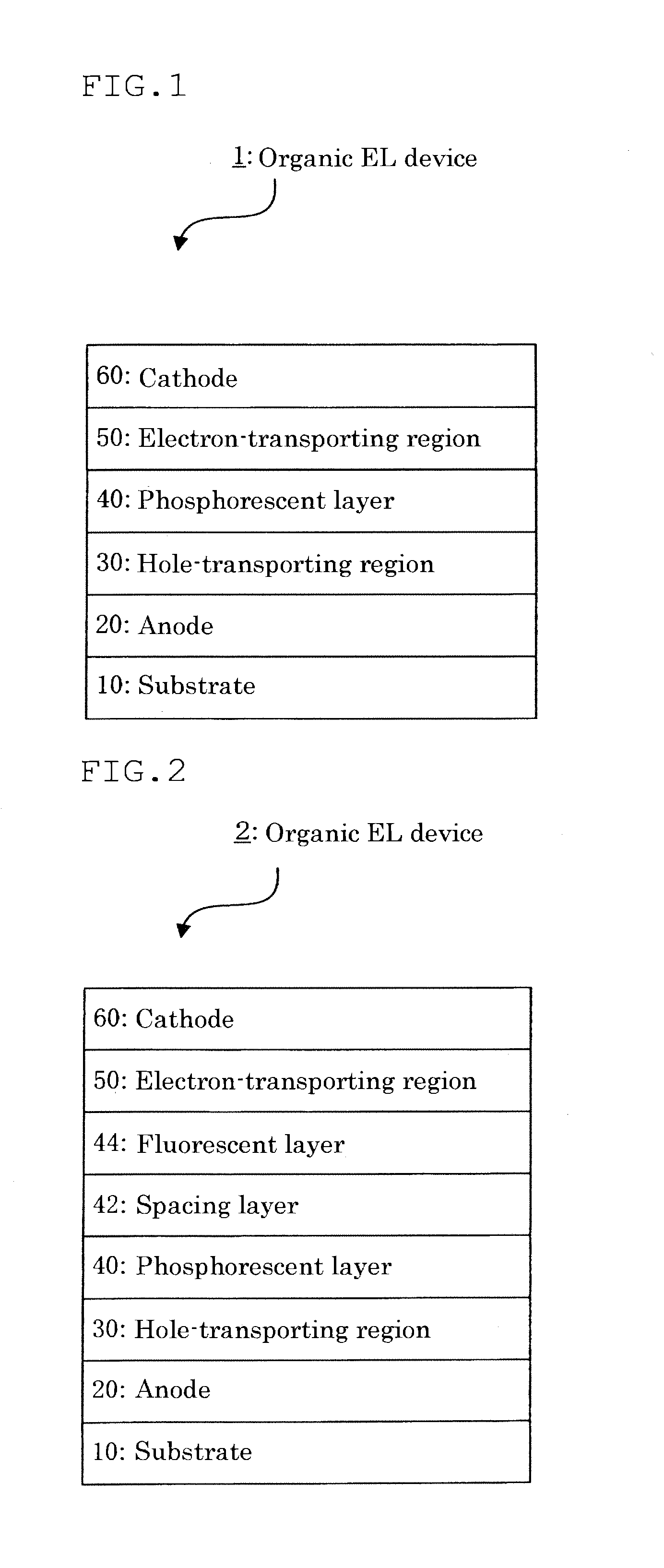
Image

Examples
synthesis example 1
Synthesis of Intermediate 3
[0146]
[0147]Under an argon atmosphere, 2.3 g (8.06 mmol) of M-2, 279 mg (0.242 mmol) of tetrakis(triphenylphosphine)palladium(0) and 2.0 g (8.06 mmol) of M-1 dissolved in 12 mL of dried toluene were placed in a three-necked flask. Further, 12 mL of dried dimethoxyethane and 12 mL of a 2M aqueous solution of sodium carbonate were added. The resulting mixture was heated under reflux while stirring for 15 hours. The reaction mixture was cooled to room temperature. After addition of water, the mixture was stirred for an hour at room temperature, followed by extraction with toluene. After separating, an organic layer was washed with saturated saline, and dried with anhydrous sodium sulfate. Under reduced pressure, the solvent is distilled away, and a residue was purified by silica-gel column chromatography to obtain 3.1 g of intermediate 1 (yield: 92%).
[0148]Under an argon atmosphere, 3.12 g (7.6 mmol) of the intermediate 1, 70 mg (0.076 mmol) of tris(dibenzyli...
synthesis example 2
Synthesis of Intermediate 6
[0151]
[0152]Under an argon atmosphere, 22.9 g (55.5 mmol) of M-3, 1.92 mg (1.67 mmol) of tetrakis(triphenylphosphine)palladium(0), 25.1 g (61.1 mmol) of phenylboronic acid, 83 mL of dried toluenene, 83 mL of dried dimethoxyethane and 83 mL of a 2M aqueous solution of sodium carbonate were placed in a three-necked flask. The mixture was heated under reflux while stirring for 8 hours. The reaction mixture was cooled to room temperature. After addition of water, the mixture was stirred for an hour at room temperature, followed by extraction with toluene. After separating, an organic layer was washed with saturated saline, and dried with anhydrous sodium sulfate. Under reduced pressure, a solvent was distilled away, and a residue was purified by silica-gel column chromatography to obtain 19.5 g of intermediate 4 (yield: 86%).
[0153]Under an argon atmosphere, 19.5 g (47.6 mmol) of the intermediate 4, 436 mg (0.476 mmol) of tris(dibenzylideneacetone)dipalladium(0...
synthesis example 3
Synthesis of Intermediate 7
[0156]
[0157]Under an argon atmosphere, 38.6 g (147 mmol) of triphenylphosphine, 16.3 g (58.8 mmol) of M-7, and 65 mL of dichlorobenzene were placed in a three-necked flask. The mixture was heated under reflux while stirring for 18 hours. The reaction mixture was cooled to room temperature and purified by silica-gel column chromatography to obtain 9.4 g of 4-bromocarbazole (yield: 65%).
[0158]Under an argon atmosphere, 4.0 g (16.3 mmol) of 4-bromocarbazole, 5.9 g (16.3 mmol) of M-8, 36 mg (0.16 mmol) of palladium acetate, 112 mg (0.32 mmol) of 2-(dicyclohexylphosphino)biphenyl, 6.8 g (32 mmol) of tripotassium phosphate and 70 mL of toluene were placed in a three-necked flask. The mixture was stirred while heating under reflux for 20 hours. The reaction mixture was cooled to room temperature, and a saturated aqueous solution of sodium hydrogen carbonate was added to the mixture, followed extraction with dichloromethane at room temperature. An organic layer ob...
PUM
| Property | Measurement | Unit |
|---|---|---|
| excited triplet energy | aaaaa | aaaaa |
| excited triplet energy | aaaaa | aaaaa |
| emission wavelengths | aaaaa | aaaaa |
Abstract
Description
Claims
Application Information