Process and rotary machine type reactor

a rotary machine type, process technology, applied in the direction of thermal non-catalytic cracking, ultra-high pressure processes, liquid hydrocarbon mixture production, etc., can solve the problems of hardly satisfactory modern requirements of cost-effective feedstock utilization, inability to increase reaction temperature, and feedstock residence time, so as to overcome limitations in heat supply speed and yield the desired pyrolysis product. , the effect of reducing pressur

Active Publication Date: 2014-08-28
COOLBROOK
View PDF2 Cites 17 Cited by
  • Summary
  • Abstract
  • Description
  • Claims
  • Application Information

AI Technical Summary

Benefits of technology

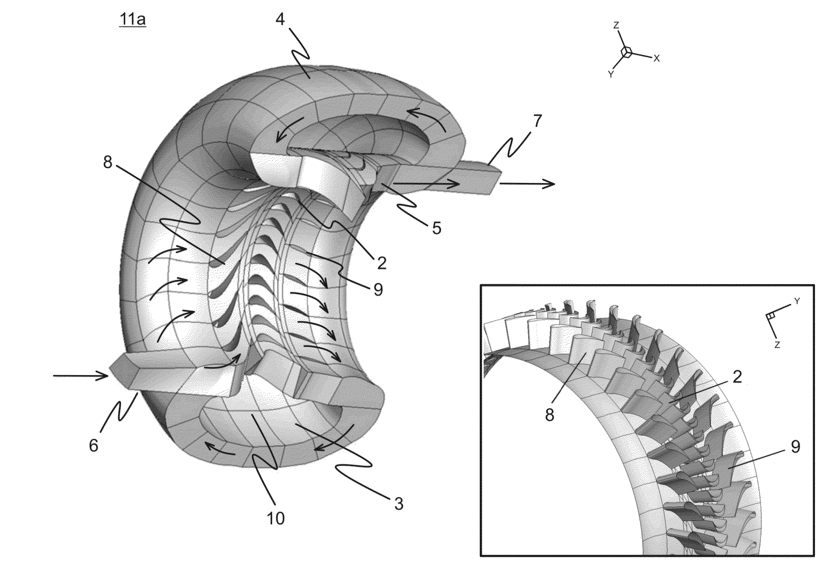
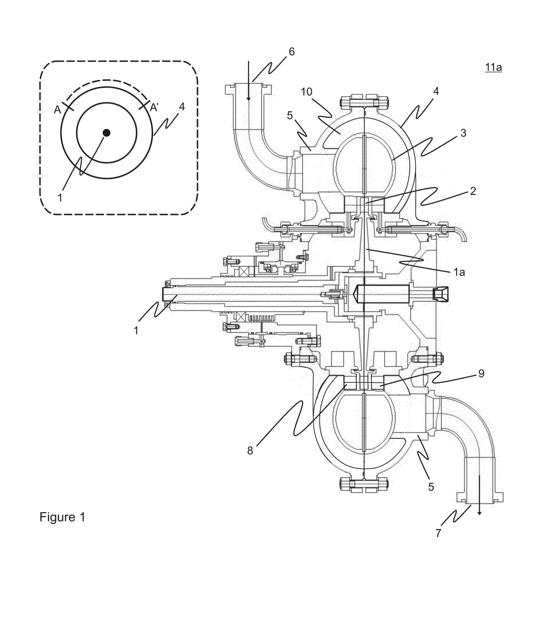
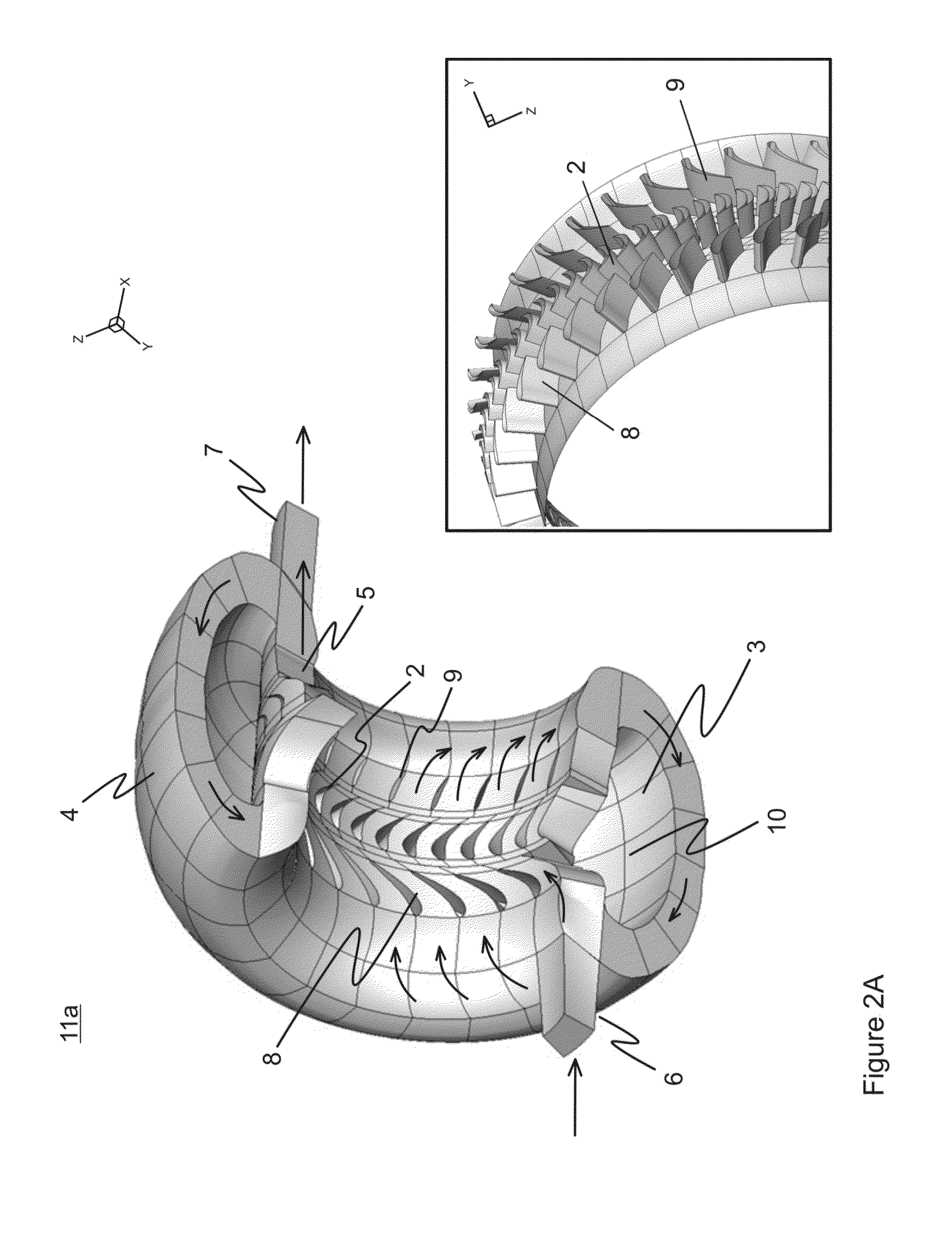
[0026]The decomposition reactions in the reactor take place due to heat generated directly in feedstock containing process stream when it passes through series of stationary shock waves of high intensity. Such method of heat supply enables significant decrease in temperature of the walls confining the reaction zone, thus providing an opportunity to overcome limitations in speed of heat supply, otherwise typical to tubular furnace. The time that feedstock gas spends in the reaction zone, which consists of space limited by stationary and rotor cascades and vaneless space, is very short (approximately 0.01 seconds or less), that is about 10 times shorter comparing to a conventional pyrolysis furnace. The process thus becomes more controllable than conventional thermal cracking, although chemical reactions remain substantially the same. The yield of desired pyrolysis products increases because it is possible to decrease pressure and reduce time of residence of feedstock gas in the reaction zone, as well as due to a more uniform temperature profile in a cross-section of the process stream. Since the aforesaid process is characterized with extremely high yield of main products, such as olefins, for example, the technology thus provided represents in the first place a next step in a development of cracking processes to produce additional value from a smaller amount of feedstock, such as oil and gas. Utilization of said reactors in industry enables more cost-effective processing of raw materials therefore positively effecting efficiency and profitability of oil refinement plants.
[0027]Secondly, the provision of rotary machine type reactor makes it possible to solve a coke formation problem. The reason for reduced coke formation rate in comparison to the conventional technology is lower residence time of gaseous feedstock in the reaction zone combined with lower temperatures of reactor static parts (walls). Furthermore lower residence times favour reaction selectivity towards desired products.

Problems solved by technology

Those are also issues to consider for the development of one of the main petrochemical processes—large-scale production of lower (low molecular weight) olefins.
The existing production technology for lower olefins, comprising pyrolysis of medium weight hydrocarbons, such as naphtha or gasoil and light hydrocarbons like pentanes, butanes, propane and ethane, down to lightweight substantially unsaturated polymerizable components in the tubular furnace, was created more than half a century ago and hardly satisfies modern requirements of cost-effective feedstock utilization.
Tubular furnaces have restrictions for the pyrolysis process: reaction temperature cannot be increased because tube material durability as well as heat transfer from tube walls to process gas has physical limits.
This leads to feedstock residence time, which is not optimal for the process.
Insufficient feedstock heating rate in tubular cracking furnaces lead to increased duration of pyrolysis process.
This fact results in situation, when formed at initial stages olefins reside in the reactor furnace for sufficiently long time to begin entering into secondary reactions, natural consequence of which is a loss of a target product.
Secondary product also includes coke, which causes heat transfer problems in tubes and fouling in equipment located downstream.
Traditional technology does not offer a reasonable solution for eliminating of aforesaid problem, since heat transfer rates in radiant sections of conventional pyrolysis furnaces have already reached technical limits.
Traditional process for producing low-molecular weight hydrocarbons by thermal degradation thus encounters the following problems: 1. poor performance factor for tubular furnace reactors; 2. loss of valuable feedstock material; 3. long reaction times; 4. high secondary reactions rates; 4. high energy consumption; 5. non-optimum (less than possible) product yield and selectivity.

Method used


Image

  • Process and rotary machine type reactor
  • Process and rotary machine type reactor
  • Process and rotary machine type reactor

Examples


example 1

[0102]Test drive for an exemplary helical-path reactor assembly in comparison to conventional tubular pyrolysis furnaces of different manufacturers.

[0103]The small-capacity model of the helical-path reactor was developed and manufactured to evaluate technical feasibility of a new pyrolysis process in test drive conditions. In order to perform experiments a test stand was constructed. The major objective of testing series was obtaining data on pyrolysis product yield and composition. The model reactor was thus equipped with a 90 kW electric motor with a step-up gearing to drive the rotor. Technical features of the model reactor were as follows: volume of a reaction zone: 2×10⁻³ m3; rotor rotational speed: 18,000-20,000 rpm.

[0104]Process conditions settings during test-drives of the model reactor were similar to that usually utilized in reactors of commercial scale: temperature of pyrolysis reaction was about 900° C.; feedstock residence time in reaction zone was 0.025-0.030 sec; and ...


PUM


Abstract

A rotary machine type shock wave reactor suitable for thermal cracking of hydrocarbon-containing materials includes a casing, a rotor whose periphery contains an axial-flow blade cascade, and a directing rim, provided with at least two stationary vane cascades, adjoining an axial-flow rotor cascade, wherein the casing substantially encloses the periphery of the rotor and the directing rim. The cascades are configured to direct feedstock containing process stream to repeatedly pass the cascades in a helical trajectory while propagating within the duct between the inlet and exit and to generate stationary shock-waves to heat the feedstock. The axial-flow rotor cascade is configured to provide kinetic energy and add velocity to feedstock containing process stream, and the stationary vanes located downstream the rotor cascade are configured to reduce the velocity of the stream and convert kinetic energy into heat. The reactor may also process carbohydrate- and glyceride-based feedstock, and gaseous biomass matter.

Description

FIELD OF THE INVENTION[0001]The present invention relates to the field of oil- and petrochemical refinement and in particular to the reactors for thermal cracking of hydrocarbon-containing compounds.BACKGROUND[0002]Cracking processes historically have been utilized in oil refineries and petrochemical plants to convert heavy hydrocarbon streams into lighter hydrocarbon fractions. Although the field of oil- and petrochemical refinement is referred to as one of the well-established and deep-rooted technological areas, one of the trends, emerging in oil- and petrochemical industry, requires that any developing technology would meet two major requirements. Those requirements may be briefly formulated as energy saving and reducing consumption of feedstock extracted from the non-renewable sources of raw materials. Those are also issues to consider for the development of one of the main petrochemical processes—large-scale production of lower (low molecular weight) olefins.[0003]Low-molecula...

Claims


Application Information

Patent Timeline
Patent Type & Authority Applications(United States)
IPC IPC(8): B06B1/16
CPCB06B1/167B01J3/08B01J19/1806C10G3/00C10G3/40C10G9/00Y02P30/20
Inventor SEPPALA, JUKKAHILTUNEN, JYRKIPUROLA, VELI-MATTI
Owner COOLBROOK
Why Eureka
Try Eureka