Active volume energy level large scale sub-sea energy fluids storage methods and apparatus for power generation and integration of renewable energy sources

a technology of energy fluids and active volume, which is applied in the field of energy storage systems and methods, can solve the problems of increasing world energy consumption at an alarming rate, difficult to harvest useful energy from these sources in a steady way, and sources are not predictable, so as to achieve optimized energy balance, low cost, and high pressure

Inactive Publication Date: 2014-09-18
KONUKOGLU ZEKERIYE +2
View PDF9 Cites 38 Cited by
  • Summary
  • Abstract
  • Description
  • Claims
  • Application Information

AI Technical Summary

Benefits of technology

[0023]In accordance with another aspect of the present invention, system for storing energy in fluid form includes a fluid containment structure having an interior defined by a top, one or more sides, and a bottom, the fluid containment structure being configured to be operable when filled with fluid while submerged beneath a surface of a body of water at a preselected distance from a floor of the body of water. The system also includes passage means adjacent the structure bottom for providing flow communication between the structure interior and the body of water, and conduit means operatively connected to the containment structure top for providing flow communication between a source of an energy-containing fluid adjacent the surface of the body of water; and the structure interior, wherein the flow of the energy-containing fluid entering the containment structure displaces an equivalent volume of water through the passage means. The system still further includes pumping means for providing a flow of the energy-containing gas into the containment structure interior against a back pressure essentially equal to the static pressure of the body of water at the preselected distance.
[0024]In accordance with yet another aspect of the present invention, a method for producing and storing hydrogen gas includes providing a gas containment structure having an interior defined by a top, one or more sides, and a bottom, and locating the containment structure below a surface of a body of sea water, the structure being configured for sea water flow communication between the body of sea water and the structure interior at a location adjacent the structure bottom. The method also includes selecting a material reactive with sea water to produce hydrogen gas, and transporting the material to the interior of the structure proximate the structure bottom. The method further includes evolving hydrogen gas within the structure interior by reacting the reactive material with sea water, and displacing a volume of sea water from the containment structure interior substantially equivalent to that of the evolved hydrogen gas.
[0025]Generally, this invention relates to a sub-sea, (underwater) energy storage tank system. The system is filled with the energy fluids pumped from a station located above the large body of the water. The storage system is composed of a large tank or a cluster of many interconnected tanks. The tanks are made of low cost materials including metals, concrete or impermeable membranes, synthetic fabrics or rubbers. The tanks are ballasted with dead weights or in other cases are tethered to the sea floor in order to overcome the buoyancy forces due to density differences between the storage fluid and the water, and also the forces due to prevailing underwater currents, if any. The storage system receives and delivers the energy fluid(s) through conduit(s) running between a surface station and the tanks. The surface station can be a floating platform, a tanker ship or an offshore facility or a power plant or a nearby land-based terminal. The tank bottoms are either completely open or they have large ports to allow the surrounding water to flow in and out during the discharging or charging processes respectively. The fluids are pumped using pumps, compressors, multi-phase pumps or hydraulic-based compression devices. The fluids can be in the form of liquids such as fresh water e.g.

Problems solved by technology

As is well known, world energy consumption is increasing at an alarming rate while the supply side of the fossil fuel has limited reserves.
While the potential from natural resources including solar and wind are much higher than the world power consumption, harvesting the useful energy from these sources in a steady way is very challenging.
With all of these improvements, the biggest problem is that these sources are not predictable.
Similarly, solar or ocean wave based energy generation process is not predictable either.
Battery based storage technologies are still in development stage and they are too expensive in addition to their short power discharge life.
Underground compressed air energy storage systems (CAES, only two systems in operation) are reliable but they are also very costly to construct.
The existing land based energy storage tanks used for storing compressed energy gas or liquids cannot be a comprehensive and long term solution for the energy storage problems, due to high risks to the surroundings (live-stock, hazard materials, fire).
They also have technical limitations regarding the size of the tanks.
These become very critical issues, especially when a power generation system requires large storage tanks for an optimum output from the generation plant.
Therefore, for safety reasons, and including many other factors, there is a limit to how big a tank can be constructed for given tank material(s) and internal pressure.
However, when you analyze them in detail, these prior power generation systems have many shortfalls.
The most common problems are violation of the law of physics.
Also, they may be impractical or require large capital investments and/or are based on unrealistic conditions.
The required conditions cannot be easily met to build or to op

Method used


Image

  • Active volume energy level large scale sub-sea energy fluids storage methods and apparatus for power generation and integration of renewable energy sources
  • Active volume energy level large scale sub-sea energy fluids storage methods and apparatus for power generation and integration of renewable energy sources
  • Active volume energy level large scale sub-sea energy fluids storage methods and apparatus for power generation and integration of renewable energy sources

Examples


Embodiment Construction

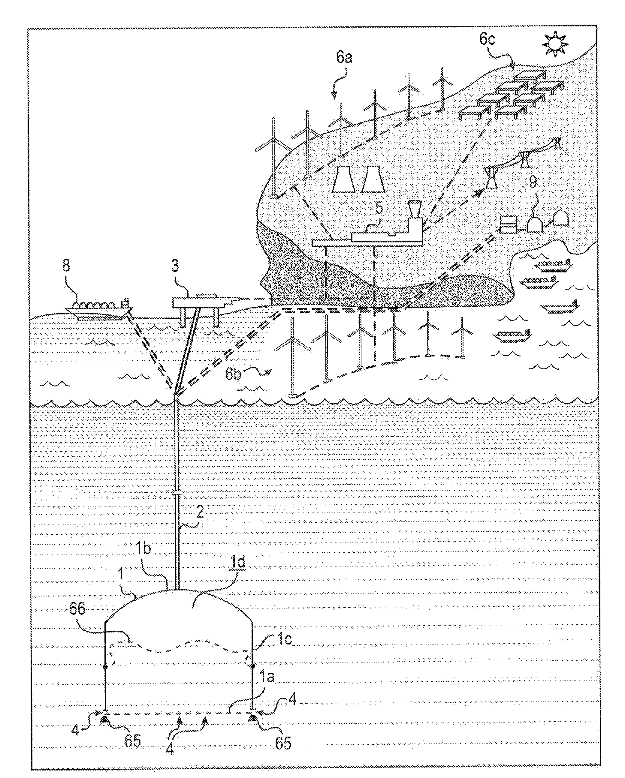
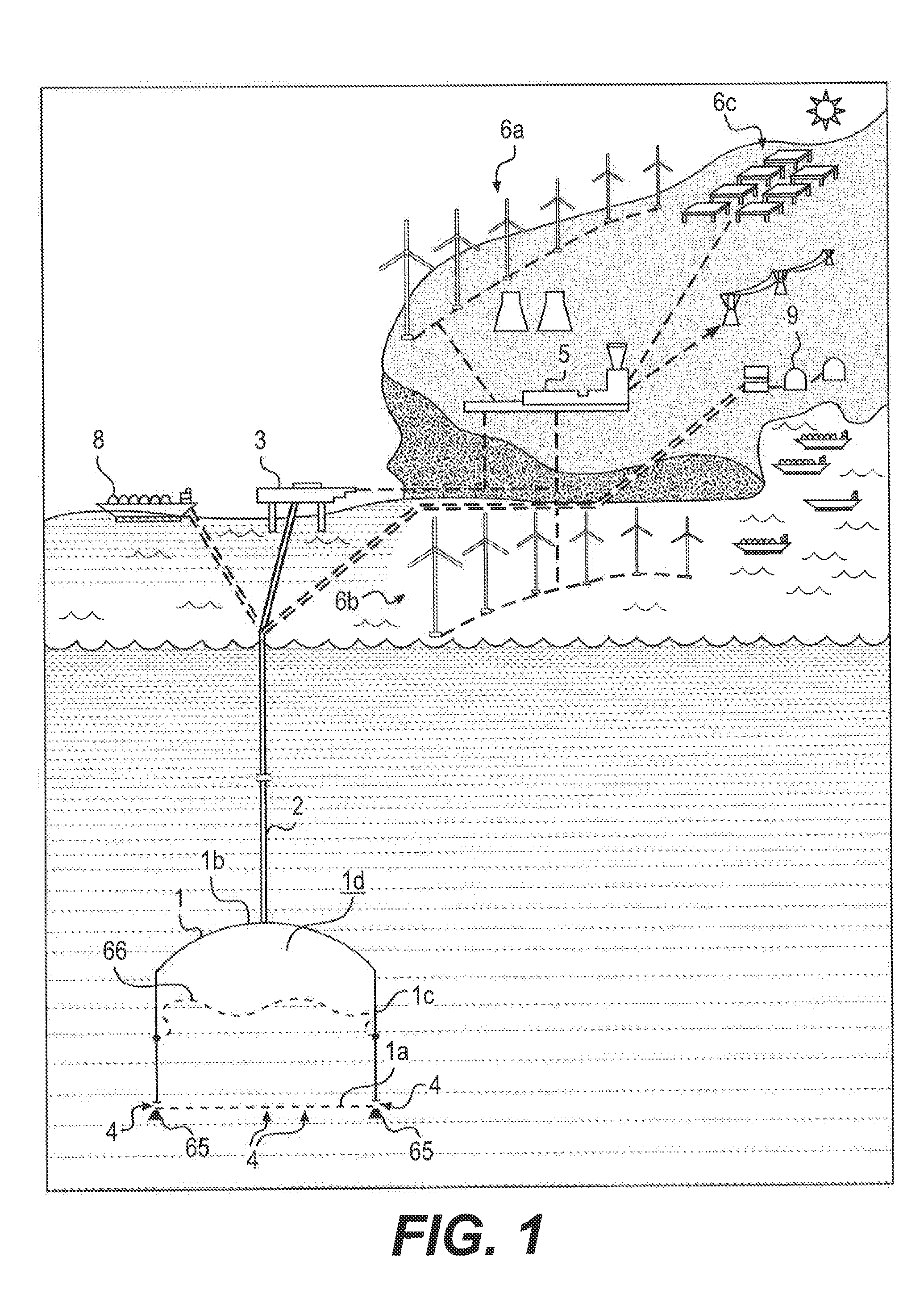
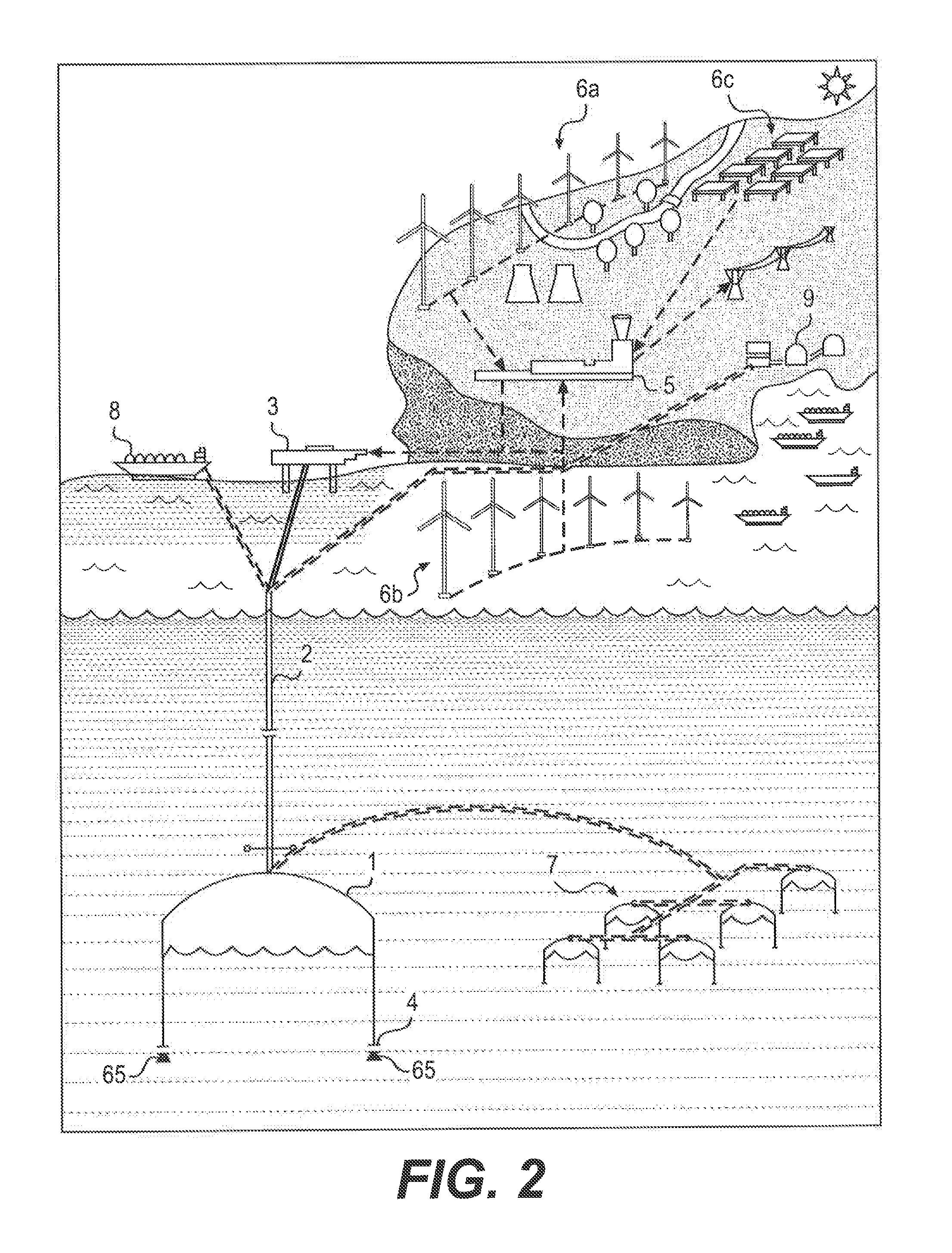
[0040]Since the natural gas being considered is less harmful to environment than liquid fossil fuels, the gas storage systems installations gained substantial momentum around the world, especially over the last 20 years. Despite increased activities in gas storage, mainly two important issues among the many others are extremely critical for the advancement of this sector. These issues are safety and the size of storage volume. However, a negative is that these two factors are inversely related. Storing a large mass of gas requires either a high compression pressure or low pressure but large storage volume. As mentioned above, these two factors are also inversely related from a safety point of view. Thus, land based fixed volume storage technology has limited capacity and has many problems including costly construction, especially large tanks at high pressures. The present invention provides a solution to the land-based gas storage problem by exploiting the high ambient pressure exis...


PUM


Abstract

Systems and methods for storing energy in gaseous form in submerged thin-walled tanks are secured to the ocean or lake floor but are open to the water at the tank bottoms and are configured to be filled with gas while submerged.
A conduit operatively connected to the tanks provides flow from a surface source of an energy-containing gas to the tank interiors. Surface or subsurface pumping apparatus which may include piston-less pressure cylinders or have leveraged pistons provide a preselected flow rate of the energy-containing gas into the containment structure interior against a back pressure essentially equal to the static pressure of the body of water at the location of the tank to displace an equivalent volume of water through the open bottom. The conduit can be configured to allow heat transfer to vaporize liquefied gas prior to storage. Hydrogen gas can be generated and stored within the tank using Aluminum activated with Galinstan.

Description

FIELD OF THE INVENTION[0001]This invention relates to energy storage systems and methods. In particular, this invention relates to underwater storage of energy-containing fluids, especially in gaseous form.BACKGROUND OF THE INVENTION[0002]As is well known, world energy consumption is increasing at an alarming rate while the supply side of the fossil fuel has limited reserves. In addition to fast depletion of the projected fossil fuel reserves (petroleum, gas and coal), their irreversible damage to the environment and atmosphere (greenhouse gas) prompted exploration the environmentally friendly, alternative energy sources. Since mid the 1970, many studies were undertaken by academia, the private sector and governments around the world looking for environmentally friendly alternative energy sources. From these studies, natural resources like the wind, solar, ocean waves, currents and biomass energy-generating technologies emerged. Especially, wind power turbines became the most accept...

Claims


Application Information

Patent Timeline
IPC IPC(8): B63G8/00C01B3/10F04F5/00
CPCB63G8/001F17C2270/0581F04F5/00C01B3/00C01B3/08C02F1/22B65D88/78C01F1/00F17C1/007F17C5/06F17C9/04F17C13/021F17C13/081C02F2103/08F17C2201/0109F17C2201/0138F17C2201/0157F17C2201/0185F17C2201/032F17C2201/035F17C2201/052F17C2201/054F17C2203/0617F17C2205/0126F17C2205/0142F17C2205/0149F17C2205/0184F17C2205/0326F17C2205/0355F17C2221/011F17C2221/012F17C2221/031F17C2221/033F17C2221/035F17C2223/0123F17C2223/0153F17C2223/0161F17C2223/0169F17C2223/0192F17C2223/033F17C2223/035F17C2225/0123F17C2225/035F17C2227/0114F17C2227/0142F17C2227/0157F17C2227/0164F17C2227/0192F17C2227/0318F17C2227/0327F17C2227/033F17C2227/039F17C2227/0395F17C2250/0413F17C2250/0491F17C2250/075F17C2260/046F17C2265/05F17C2265/07F17C2270/0123F17C2270/0128F17C2270/0136F17C2270/0152C01B3/10Y02E60/32Y02E60/36Y02P20/133
Inventor ZEREN, FEVZIKONUKOGLU, ZEKERIYE
Owner KONUKOGLU ZEKERIYE
Why Eureka
Try Eureka