
Thin film electrochemical cell with a polymer double seal

a polymer and electrochemical cell technology, applied in the field of thin film electrochemical cell with a polymer double seal, can solve the problems of insufficient resistance, prone to many problems, and inclusion of ceramic or metal physical barriers, and achieves the effects of preventing the diffusion of deleterious substances, and reducing the number of electrochemical cells

Active Publication Date: 2014-12-11
ELECTROVAYA
View PDF2 Cites 14 Cited by
  • Summary
  • Abstract
  • Description
  • Claims
  • Application Information

AI Technical Summary

Benefits of technology

The present invention provides a thin film electrochemical cell packaging that provides a sufficient seal from the external environment and also helps in heat dissipation and uniform temperature distribution within the cell. The inclusion of embedded particles in the second polymer layer provides better heat transfer characteristics. The use of two polymer layers with weak points offset from each other increases structural integrity and reduces the likelihood of deleterious substances entering the cell. This results in a longer-lasting, better-performing battery cell.

Problems solved by technology

Such a sheet would provide multiple layers, but may not be thick enough to provide sufficient resistance to the undesired diffusion of chemical species in applications such as lithium ion batteries.
The sheet provides a single seal, leaving it prone to many problems.
For thin film battery cells, where diffusion is the primary concern rather than physical breach, the inclusion of a ceramic or metal physical barrier adds unnecessary weight, expense and complexity.
Again, laminate foils alone do not provide sufficient protection.
1. They exhibit poor diffusive resistance. Electrochemical cells, and in particular lithium ion cells, react in an undesirable manner with atmospheric components such as water vapour, oxygen, nitrogen and carbon dioxide, damaging the cell components. In cells comprising a liquid electrolyte, the electrolyte may also diffuse out of the cell.
2. They are generally fragile and are easily nicked or torn. The seal may be breached through mechanical or thermal shocks. This can cause electrolyte leakage, which impairs battery performance and introduces dangerous high voltage connections.
3. The aluminum in the foil may cause voltage leakages. During cell packaging, the foil is generally freshly cut. Not enough time elapses for the aluminum to develop an electrically insulating oxide layer, so conductive pure aluminum is exposed. This may result in voltage leakage or short circuits, particularly at the terminals.
This addresses many of the problems listed, but is expensive and requires precision tooling.
These containers corrode over time due to voltage ingress, eventually rendering them useless.
This solitary epoxy seal provides only limited protection against diffusion.
With respect to the problems listed above, this arrangement is not a significant improvement over laminate foils.
Furthermore, improper epoxy curing processes can lead to degradation of some metals in contact with said epoxy.
Such a method of sealing cells within a battery module by the use of sheets with inserts applies only to battery modules comprising a plurality of cells arranged in a line, and does not allow for the packaging of individual cells nor variance in geometrical arrangement.
Another challenging aspect of thin film battery cells, as for example lithium ion batteries found in most portable electronic devices, electric vehicles, and other applications, relates to thermal management.
High temperatures increase the rate of exothermic intracellular reactions, which increase the rate of heat generation, leading to even higher temperatures.
This situation is know as thermal runaway and is damaging to the cell, sometimes leading to combustion or explosion.
In addition to destroying the battery, this also poses a safety risk.
These higher temperature areas degrade more quickly and impair performance compared to the cooler areas of the cell.

Method used


Image

  • Thin film electrochemical cell with a polymer double seal
  • Thin film electrochemical cell with a polymer double seal
  • Thin film electrochemical cell with a polymer double seal

Examples


Embodiment Construction

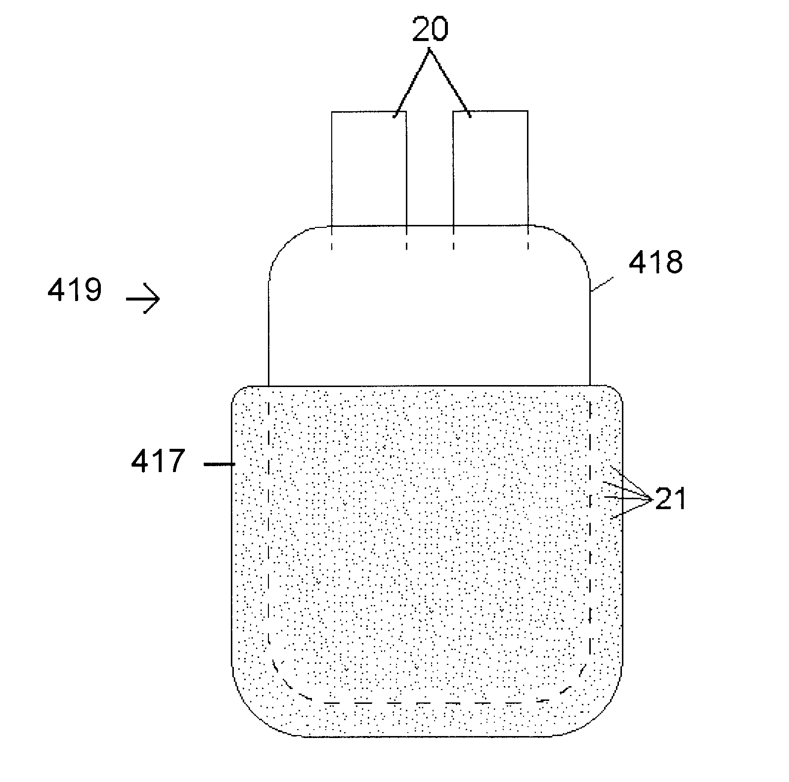
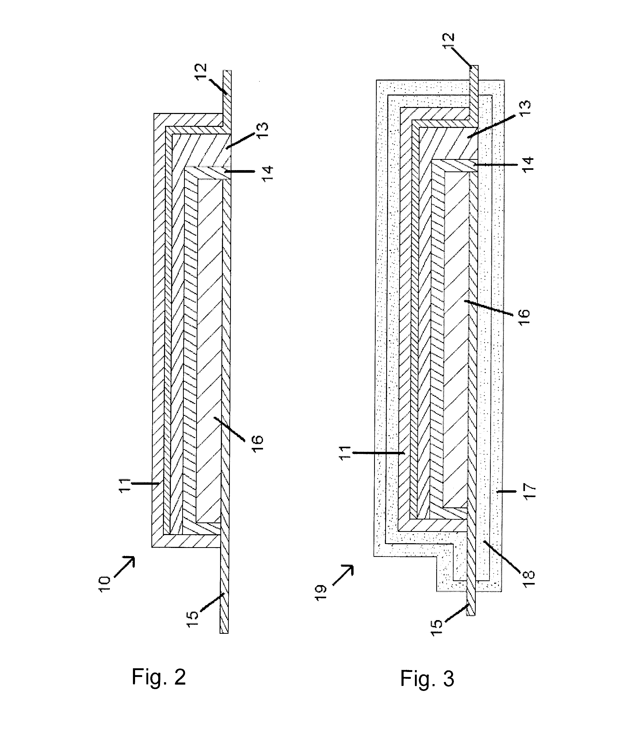
[0040]Reference may now be made to FIG. 2 which illustrates an electrode assembly 10 of a thin film electrochemical cell. The electrode assembly 10 includes a cathode current collector 15, a cathode 16, an electrolyte 14, an anode 13 and an anode current collector 12. The electrode assembly 10 further includes a passivation layer 11, which may not be included in alternate embodiments. Alternate embodiments may further comprise separator layers within the electrode assembly 10, which are not pictured in the preferred embodiment shown. The cathode 16 is preferably made of a lithium intercalation compound, preferably a metal oxide such as LiNiO2, LixMn2O4 or LiCoO2. The electrolyte 14 is preferably a composite polymer electrolyte as disclosed in U.S. Pat. No. 6,753,114, which is specifically incorporated herein by reference. Alternate embodiments may include other solid or liquid electrolytes. The anode 13 is preferably made of a tin compound, such silicon-tin oxynitride, SiSnON, when ...


PUM


Abstract

A double-sealed thin film electrochemical pouch cell, comprising a cathode current collector, a cathode, an electrolyte, an anode, and an anode current collector, which is double-sealed by a first inner laminate layer forming a primary seal covered by a second outer polymer layer forming a secondary seal. The second outer polymer layer comprises embedded particles to increase the thermal conductivity of the second outer polymer layer.

Description

RELATED APPLICATION[0001]This application claims the benefit of 35 USC 119(e) to U.S. Provisional Application Ser. No. 61 / 631,453 filed 5 Jan. 2012 (May 1, 2012) and U.S. Provisional Application Ser. No. 61 / 631,457 filed 5 Jan. 2012 (05.01.2012).SCOPE OF THE INVENTION[0002]This invention relates to thin film electrochemical cells, and more particularly, thin film battery cells having first and second polymer sealing layers.BACKGROUND OF THE INVENTION[0003]Thin film battery cells are typically heat sealed in soft aluminum / plastic laminate foil pouches. U.S. Pat. No. 6,284,406 discloses a thin film cell battery sealed by a sheet of flexible laminate material having at least one metal foil layer and a layer of an adhesive-like polymeric material. Such a sheet would provide multiple layers, but may not be thick enough to provide sufficient resistance to the undesired diffusion of chemical species in applications such as lithium ion batteries. The sheet provides a single seal, leaving it...

Claims


Application Information

Patent Timeline
IPC IPC(8): H01M2/08H01M10/617H01M50/126H01M50/133H01M50/141
CPCH01M10/5008H01M2/08H01M10/617Y02E60/10H01M50/124H01M50/581H01M50/126H01M50/133H01M50/141
Inventor BHOLA, RAKESHDAS GUPTA, RAJSHEKARDAS GUPTA, SANKAR
Owner ELECTROVAYA
Learn More