

Redox flow secondary battery and electrolyte membrane for redox flow secondary battery
- Summary
- Abstract
- Description
- Claims
- Application Information
AI Technical Summary
Benefits of technology
Problems solved by technology
Method used
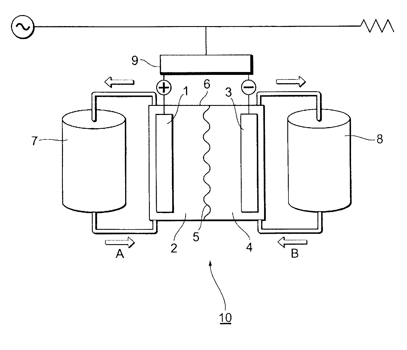
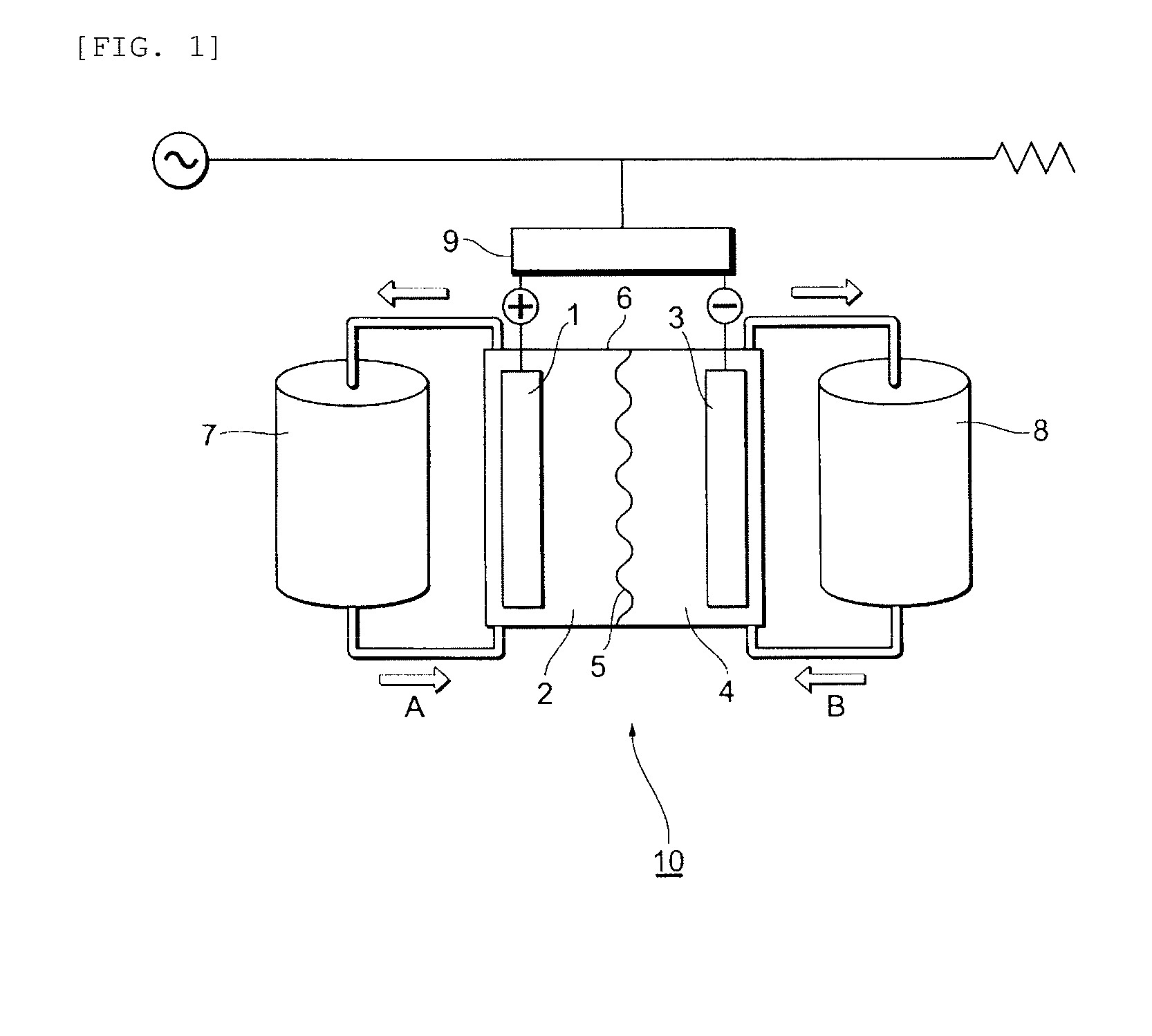
Image

Examples
examples
[0167]Then, the present embodiments will be described more specifically by way of Examples and Comparative Examples, but the present embodiments are not limited to the following Examples unless going over their gist.
[Measurement Methods]
[0168](1) The melt flow index of a PFSA resin precursor
[0169]The melt flow index was measured according to ASTM: D1238 under the measurement conditions of a temperature of 270° C. and a load of 2,160 g.
(2) The measurement of an equivalent weight EW of a PFSA resin
[0170]0.3 g of a PFSA resin was immersed in 30 mL of a saturated NaCl aqueous solution at 25° C., and left for 30 min under stirring. Then, free protons in the saturated NaCl aqueous solution was subjected to a neutralization titration using a 0.01 N sodium hydroxide aqueous solution with phenolphthalein as an indicator. The end point of the neutralization titration was set at a pH of 7; and the PFSA resin portion, obtained after the neutralization titration, in which counter ions of ion-exc...
examples 1 to 8
(1) Fabrication of a PFSA Resin Precursor
[0181]A 10% aqueous solution of C7F15COONH4 and pure water were charged in a stainless steel-made stirring-type autoclave, and the interior atmosphere of the autoclave was sufficiently replaced by vacuum and nitrogen; and thereafter, tetrafluoroethylene (CF2═CF2, TFE) gas was introduced, and the interior pressure was boosted up to 0.7 MPa in terms of gage pressure. Then, an ammonium persulfuric acid aqueous solution was injected to initiate the polymerization. While in order to replenish TFE consumed by the polymerization, TFE gas was continuously fed so as to hold the pressure of the autoclave at 0.7 MPa, CF2═CFO(CF2)2—SO2F of an amount corresponding to 0.70 times the amount of TFE fed in mass ratio was continuously fed to carry out the polymerization by regulating the polymerization condition in a best range respectively to thereby obtain various perfluorocarbonsulfonic acid resin precursor powder. The MFI of the obtained PFSA resin precurs...
PUM
| Property | Measurement | Unit |
|---|---|---|
| Temperature | aaaaa | aaaaa |
| Percent by mass | aaaaa | aaaaa |
| Percent by mass | aaaaa | aaaaa |
Abstract
Description
Claims
Application Information