X-ray illuminators with high flux and high flux density
Inactive Publication Date: 2015-07-09
SIGRAY INC
View PDF7 Cites 44 Cited by
Summary
Abstract
Description
Claims
Application Information
AI Technical Summary
This helps you quickly interpret patents by identifying the three key elements:
Problems solved by technology
Method used
Benefits of technology
[0040]The higher brightness is achieved in part through the use of novel configurations for x-ray targets used in generating x-rays from electron beam bombardment. These x-ray target configurations may comprise a number of microstructures of one or more selected x-ray generating materials fabricated in close thermal contact with (such as embedded in or buried in) a substrate with high thermal conductivity, such that the heat is more efficiently drawn out of the x-ray generating material. This in turn allows bombardment of the x-ray generating material with higher electron density and/or higher energy electrons, which leads to greater x-ray brightness and therefore greater x-ray flux.
[0041]A significant advantage to some embodiments is that the orientation of the microstructures allows the use of an on-axis collection angle, allowing the a
Problems solved by technology
Designing and constructing illuminators for applications of x-rays can therefore be particularly challenging.
For scientific studies of materials, where high brightness may be needed to obtain adequate signal-to-noise ratios over a range of x-ray energies, conventional x-ray sources using electron bombardment are simply not adequate.
However, these facilities are large, often occupying acres of land, and expensive to operate, and obtaining beamtime can take months of waiting.
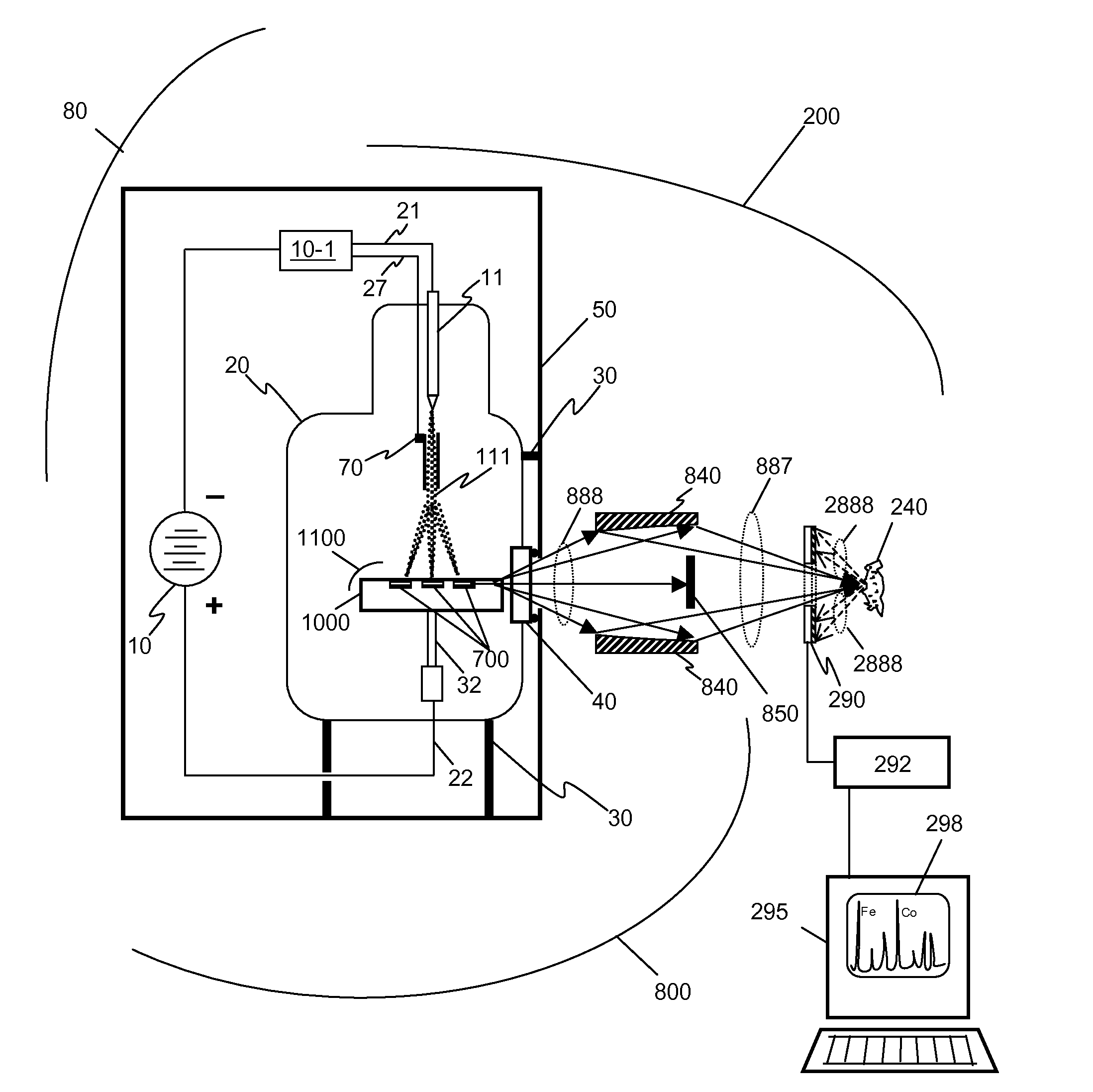
The main problem for producing such a system is the lack of a suitable system with an x-ray source and efficient optics for achieving a tightly focused, high flux and high flux density x-rays.
However, synchrotrons are large facilities, often taking up acres of land, and beam time is not available for routine analysis.
Laboratory systems have been designed using similar x-ray optics, but typically cannot achieve the brightness or x-ray flux possible with synchrotron systems.
The perceived disadvantage of laboratory microXRF is that the excitation spot is too large (typically around 30 microns).
The spot size is limited due to the low throughput at smaller spot sizes, caused by a combination of low flux at the sample and low solid angle of collection for the x-ray fluorescence.
Though LA-ICPMS generally offers lower (better) relative detection limit for metals with Z>30 and a unique ability to detect isotopes, it is destructive of the sample (via ablation), has an inferior absolute detect
Method used
Image
Click on the blue label to locate the original text in one second.
Reading with bidirectional positioning of images and text.
Examples
Embodiment Construction
1. A Basic Embodiment of the Invention.
[0091]FIG. 7 illustrates an embodiment of an x-ray fluorescence system 200 comprising an illumination system according to the invention. The fluorescence system 200 comprises an illumination system 800 which comprises an x-ray source 80 and x-ray collecting optics 840. The fluorescence system 200 additionally comprises a detector 290 with analysis electronics 295. The source 80 comprises a vacuum environment (typically 10−6 torr or better) commonly maintained by a sealed vacuum chamber 20 or active pumping, and manufactured with sealed electrical leads 21 and 22 that pass from the negative and positive terminals of a high voltage source 10 outside the tube to the various elements inside the vacuum chamber 20. The source 80 will typically comprise mounts 30 which secure the vacuum chamber 20 in a housing 50, and the housing 50 may additionally comprise shielding material, such as lead, to prevent x-rays from being radiated by the source 80 in un...
PUM
Abstract
This disclosure presents systems for x-ray illumination that have an x-ray brightness several orders of magnitude greater than existing x-ray technologies. These may therefore useful for applications such as trace element detection or for micro-focus fluorescence analysis.
The higher brightness is achieved in part by using designs for x-ray targets that comprise a number of microstructures of one or more selected x-ray generating materials fabricated in close thermal contact with a substrate having high thermal conductivity. This allows for bombardment of the targets with higher electron density or higher energy electrons, which leads to greater x-ray flux.
The high brightness/high flux x-ray source may then be coupled to an x-ray optical system, which can collect and focus the high flux x-rays to spots that can be as small as one micron, leading to high flux density.
Description
CROSS-REFERENCE TO RELATED APPLICATIONS[0001]This Patent Application claims the benefit of U.S. Provisional Patent Application No. 61 / 912,478, filed on Dec. 5, 2013, 61 / 912,486, filed on Dec. 5, 2013, 61 / 946,475, filed on Feb. 28, 2014, and 62 / 008,856, filed on Jun. 6, 2014, all of which are incorporated herein by reference in their entirety.FIELD OF THE INVENTION[0002]The embodiments of the invention disclosed herein relate to a high-brightness x-ray illumination system, and in particular, to an x-ray illuminator with high x-ray flux and high flux density suitable for use in micro-x-ray fluorescence (XRF) systems. Such systems may be useful for a variety of applications, including mineralogy, trace element detection, structure and composition analysis, metrology, as well as forensic science and diagnostic systems.BACKGROUND OF THE INVENTIONIntroduction.[0003]X-rays are a very useful form of radiation to see into materials because most materials are quite transparent to x-rays: the ...
Claims
Application Information
Patent Timeline
Application Date:The date an application was filed.
Publication Date:The date a patent or application was officially published.
First Publication Date:The earliest publication date of a patent with the same application number.
Issue Date:Publication date of the patent grant document.
PCT Entry Date:The Entry date of PCT National Phase.
Estimated Expiry Date:The statutory expiry date of a patent right according to the Patent Law, and it is the longest term of protection that the patent right can achieve without the termination of the patent right due to other reasons(Term extension factor has been taken into account ).
Invalid Date:Actual expiry date is based on effective date or publication date of legal transaction data of invalid patent.