However, considerable maintenance is required for the overhead power cables, for example on account of arcing which occurs when the power pickoff arrangements are moved relative to the overhead power cables when in operation.
Such power transfer is insufficient to meet contemporary power requirements for electric vehicles which often employ
electric drive trains with electric motors of 10 kW or greater.
Despite being proposed on many occasions in earlier patent applications and granted patents,
wireless inductive power coupling for road vehicles has not been generally adopted within contemporary
transport infrastructure.
A reason for such lack of adoption may arise on account of high initial installation cost of road-embedded inductive coils and low
petroleum prices.
Despite
successful operation of these systems, they have not been adopted into road vehicle applications, primarily on account of major infrastructure changes required and corresponding installation of vehicle fitments.
However, considerable maintenance is required for the overhead power cables, for example on account of arcing which occurs when the power pickoff arrangements are moved relative to the overhead power cables when in operation.
Moreover, a resonant power coupling apparatus which covers the underside of the vehicle results in impaired cooling to the
exhaust pipe.
Moreover, implementing the resonant power coupling apparatus to occupy less area reduces a performance of the apparatus to couple power for gaining access the
exhaust pipe.
However, considerable maintenance is required for the overhead power cables, for example on account of arcing which occurs when the power pickoff arrangements are moved relative to the overhead power cables when in operation.
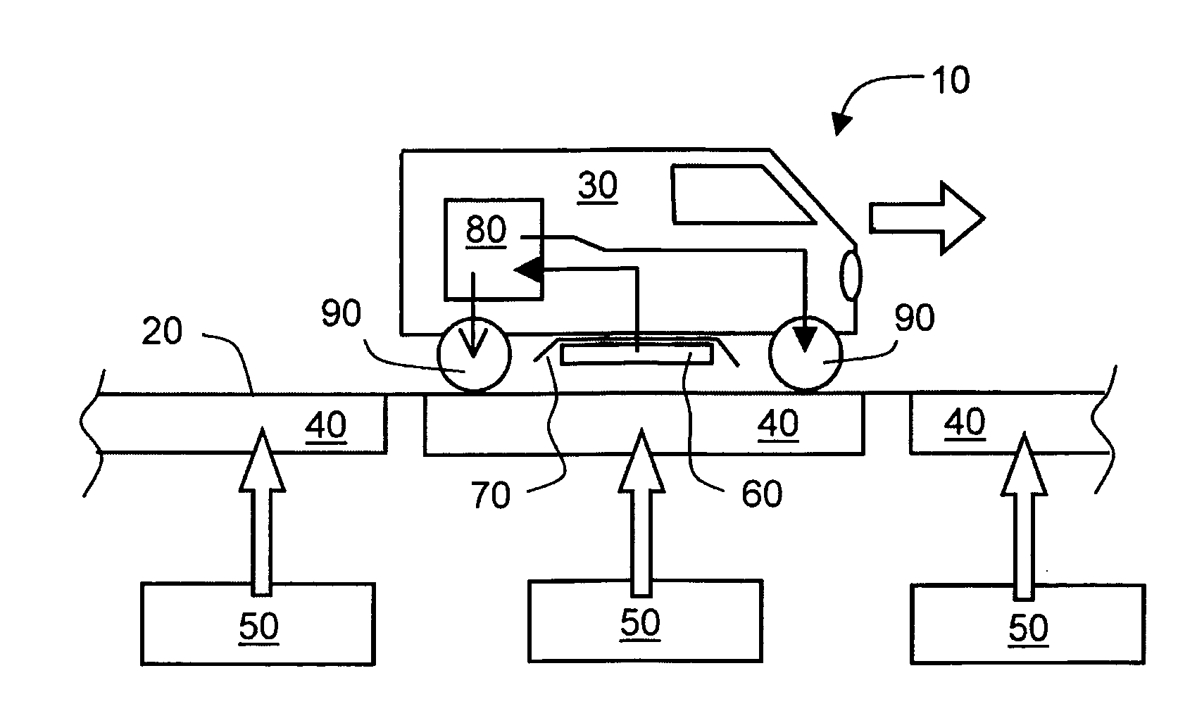
Such a relatively small clearance, for example in a range of 10 cm to 20 cm, potentially represents a safety
hazard when vehicles are travelling a high speeds, for example 120 km / hour, upon the roadway, especially when there is a risk of loose objects, namely debris being present on the upper surface of the roadway.
Such loose objects risk being wedged under the vehicles and damaging their respective
pickup coil.
A conventional manner to address this risk is to employ larger clearances and increase an area or number of turns included on the
pickup coil, but potentially adds considerably to cost.
Despite the aforementioned
wireless-powered electrical supply arrangement being described in December 1975, the arrangement has not been adopted into general use, presumably on account of
petroleum being plentiful and there being little impetus to employ alternative vehicle propulsion technologies.
However, considerable maintenance is required for the overhead power cables, for example on account of arcing which occurs when the power pickoff arrangements are moved relative to the overhead power cables when in operation.
A problem with the electrical supply arrangement described in aforesaid patent no.
In an event of
road debris or occluding material, for example
snow, being present upon a
road surface above the one or more current conductors, there arises a risk of the
road debris or occluding material damaging an underside of the vehicle, for example causing damage to the one or more conductors.
When high vehicle speeds are employed, for example greater than 50 km / hour, the
road debris or occluding material can potentially cause accidents.
Conventionally, careful maintenance of roadways to remove the road debris or occluding material would be considered necessary, but such maintenance is not economically feasible to achieve in practice for all sections of road equipped with the one or more current conductors.
Safety issues can relate to one or more of the following:(a)
exposure of personnel to high-power alternating electromagnetic fields which can potentially represent a
biological hazard;(a)
electrical shock risk to personnel when circuit cable windings embedded into a roadway are faulty or damaged, resulting in a breakdown of cable insulation;(b)
corrosion causing damage to conductors of circuit cable windings embedded into the roadway, resulting in an increase in cable resistance and associated resistive power losses when excited in operation, namely losses which are potentially spatially concentrated and can result in
fire risk by setting adjacent
asphalt and / or cable insulation into
combustion; and(c) gross roadway surface damage which can potentially result in circuit cable windings being severed and exposed at a surface of the roadway, representing an
electrical shock hazard, for example as a consequence of Earthquake, road
subsidence or
major road accident.
Moreover, the aforesaid electrical supply arrangement requires a complex configuration of coil windings to be installed in a roadway which is costly and
time consuming.
Such cost and complication represent a technical problem which dissuades implementation of inductively-coupled vehicle roadways, thus favouring contemporary alternatives such as continuing to employ Carbon-fuel driven vehicles and / or to employ vehicles with large heavy rechargeable batteries, for example sealed Lead-acid accumulators which are environmentally damaging and
Lithium batteries which represent a potential
fire risk.
Moreover, resource limitations on battery materials, for example World supply of
Lithium, prevents a majority of road vehicles in the World being implemented as electric rechargeable vehicles.
Furthermore, heavy rechargeable batteries in road vehicles is undesirable from a safety viewpoint on account of
kinetic energy KE in the road vehicles being given by ½ mV2, wherein m is a
mass of the vehicle, and V is a velocity of the vehicle when in motion.
There thus arises a problem of implementing an inductively-coupled roadway for providing
motive power to electric and
hybrid vehicles in a manner which is commercially more attractive and more straightforward to implement in comparison to known arrangements and systems.
On account of metals requiring considerable energy in their mining,
processing and
adaptation into products such as electrical cables, transformers and weatherproof housings for example, it is anticipated that
metal thefts will become a major problem in the future.
When such theft concerns infrastructure such as cables along sides of railway tracks, theft of such cables for their
metal content can be highly disruptive to reliable operation of such infrastructure.
Moreover, damage caused by hasty cable thefts can be very costly to repair, often much more costly than merely
metal value of the cables themselves.
GB 1418128, a problem potentially arises when cables embedded into road surfaces for implementing such roadways are stolen on account of their
scrap metal value.
A conventional approach would be to employ an army of roadway policemen and roadway policewomen in situ to keep watch of roadways, namely to arrest promptly any thieves who attempt to steal roadway-embedded cables; such an approach would be extremely expensive, although it could assist to reduce contemporary unemployment in a post “peak-oil” society.
A yet alternative conventional approach would be to embed the cables is such a mechanically secure manner into roadways that theft would be difficult to undertake by unauthorized parties.
However, such secure embedding of cables renders them difficult to access in an event that authorized parties are required to replace or to repair the cables.
Moreover, operating surveillance equipment is costly in personnel time, wherein personnel remotely monitor
surveillance camera images for traces of theft or potentially thieving activities.

