Scintillator panel and method for manufacturing the same (as amended)

a technology of scintillator and scintillator plate, which is applied in the direction of optical radiation measurement, fluorescence/phosphorescence, instruments, etc., can solve the problems of low s/n ratio, limited size of formable scintillator plate, and fpd has a problem, so as to reduce the width of the barrier rib, efficient guide, and high luminous efficiency

Active Publication Date: 2015-10-29
TORAY IND INC
View PDF8 Cites 11 Cited by
  • Summary
  • Abstract
  • Description
  • Claims
  • Application Information

AI Technical Summary

Benefits of technology

[0013]Production of a scintillator panel having high luminous efficiency and is capable of realizing clear images requires technology for processing a barrier rib, capable of processing with high acc

Problems solved by technology

However, the FPD has a problem such as a low S/N ratio.
However, in the method of etching a silicon wafer, the size of a formable scintillator panel is limited by the size of the silicon wafer, and a scintillator panel having a large size of 500 mm square could not be obtained.
However, it is difficult to produce the scintillator panel in view of accuracy, and a large-area scintillator panel was scarcely produced.
In the multi-layer screen printing method using a glass paste, it is difficult to process with high accuracy due to a dimensional variation o

Method used


Image

  • Scintillator panel and method for manufacturing the same (as amended)
  • Scintillator panel and method for manufacturing the same (as amended)

Examples


example 1

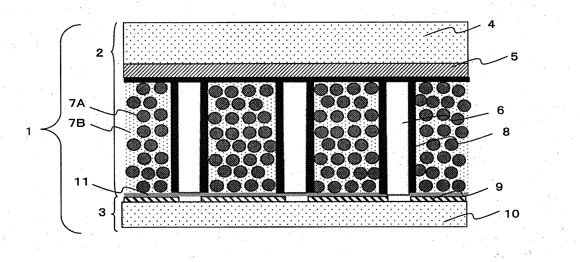
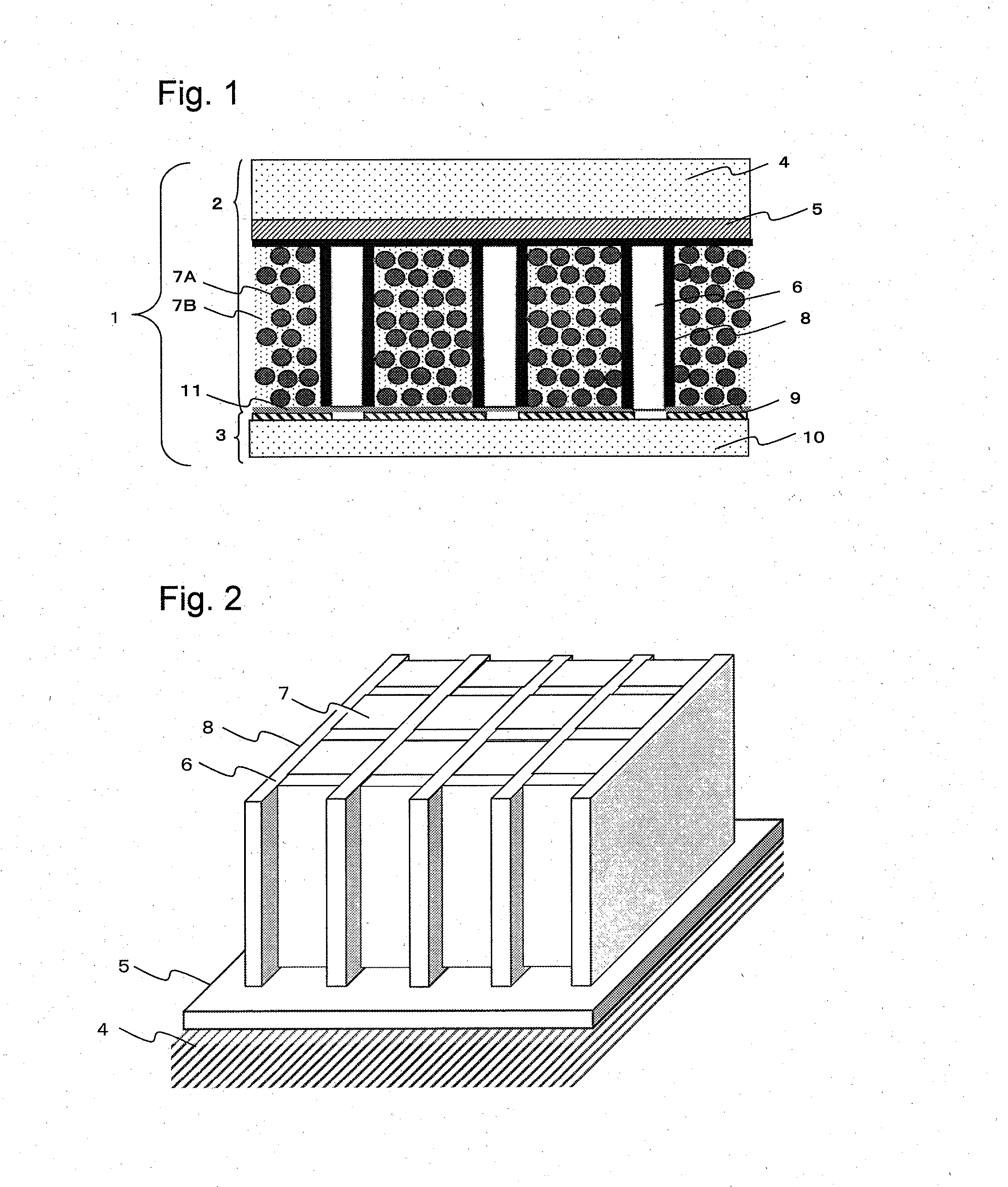
[0151]On a glass substrate having a size measuring 500 mm×500 Mm×0.5 mm in thickness (AN-100, manufactured by ASAHI GLASS CO., LTD.), the paste for underlayer was applied in a thickness of 15 μm by a bar coater, dried at 150° C. for 30 minutes, and then thermally cured to form a 12 μm thick underlayer paste film. Next, the photosensitive paste for barrier rib was applied by a die coater so as to obtain a dry thickness of 500 μm, and then dried at 120° C. for 30 minutes to form a photosensitive paste coating film for barrier rib.

[0152]Next, the photosensitive paste coating film for barrier rib was exposed at an exposure dose of 700 mJ / cm2 by an ultra-high pressure mercury lamp through a photomask having an opening corresponding to a desired barrier rib pattern (chrome mask having a grid-like opening having a pitch of 125 μm and a line width of 10 μm). The exposed photosensitive paste coating film for barrier rib was developed in an aqueous 0.5 mass % ethanolamine solution to remove t...

example 2

[0157]In the same manner as in Example 1, a substrate including a grid-like barrier rib formed thereon was produced. Next, an aluminum reflecting layer was formed on the entire barrier rib using a batch type sputtering system (“SV-9045”, manufactured by ULVAC, Inc.). The thickness of the aluminum reflecting layer in the vicinity of the barrier rib top was adjusted to 300 nm. At this time, the aluminum reflecting layer exhibits a reflectance of 90%.

[0158]Next, a gadolinium polysulfide powder Gd2O2S (Gd2O2S:Tb) having an average particle diameter Dp of 6 μm and a refractive index of 2.2 as a phosphor was mixed with a thermally curable silicone resin having an average refractive index of 1.55 as a binder resin in a mass ratio of 9:1, and a space divided by the barrier rib was filled with the mixture, and then the silicone resin was cured by heating at 140° C. for 30 minutes to produce a scintillator panel, thus producing a radiation detection device in the same manner as in Example 1. ...


PUM


Abstract

The present invention provides a scintillator panel which is provided with a narrow-width barrier rib with high accuracy in a large area, and also has high luminous efficiency and realizes clear image quality. The present invention provides a scintillator panel including a sheet-like substrate, a barrier rib provided on the substrate, and a scintillator layer filled in cells divided by the barrier rib, wherein the barrier rib is made of a material containing a low melting point glass as a main component, and the scintillator layer is made of a phosphor and a binder resin.

Description

CROSS REFERENCE TO RELATED APPLICATIONS[0001]This is the U S . National Phase application of PCT / JP2013 / 081279, filed Nov. 20, 2013, which claims priority to Japanese Patent Application No. 2012-257214, filed Nov. 26, 2012, the disclosures of each of these applications being incorporated herein by reference in their entireties for all purposes.FIELD OF THE INVENTION[0002]The present invention relates to a scintillator panel used in a radiation detection device which is used for a medical diagnostic apparatus, a nondestructive inspection instrument, and the like.BACKGROUND OF THE INVENTION[0003]Heretofore, X-ray images using films have widely been used in medical settings. However, the X-ray image using a film provides analog image information, and thus digital radiation detection devices such as computed radiography (CR) and flat panel radiation detection devices (flat panel detectors: FPDs) have recently been developed.[0004]In a flat panel X-ray detector (FPD), a scintillator pane...

Claims


Application Information

Patent Timeline
IPC IPC(8): G01T1/20G03F7/40
CPCG03F7/40G01T1/2002G01T1/20G21K4/00G01T1/20183G01T1/202
Inventor KINOSHITA, HIDEKIHAMANO, TSUBASAOKAMURA, MASAKI
Owner TORAY IND INC
Why Eureka
Try Eureka