
Nuclear fusion using high energy charged particle convergence at a target cathode

a high energy charged particle and target cathode technology, applied in nuclear reactors, nuclear engineering, greenhouse gas reduction, etc., can solve the problems of unsustainable fusion process, uncompromising new energy architecture/paradigm, and inability to scale up to produce a power plant, etc., to achieve higher fusion rate and energy production, increase the amount of fusion energy produced, and the effect of increasing the reactant density

Inactive Publication Date: 2015-11-26
GOLDBERG ADAM S
View PDF3 Cites 8 Cited by
  • Summary
  • Abstract
  • Description
  • Claims
  • Application Information

AI Technical Summary

Benefits of technology

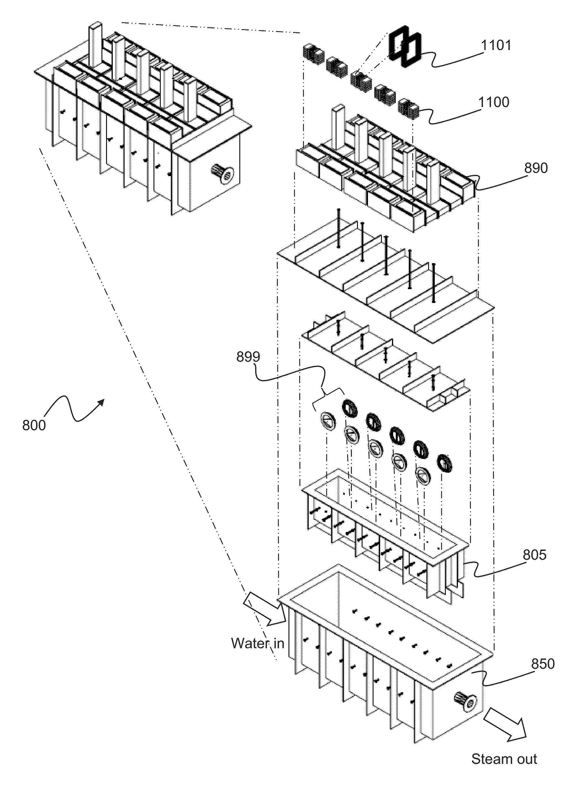
This patent is about a new system and method for generating nuclear fusion energy using a high-energy charged particle convergence at a target cathode. The system has several technical advantages: it produces a sustained series of fusion reactions, uses a higher reactant density of the deuterium and tritium gases, requires less energy input, can operate at a higher cycle frequency, has a practical heat exchange method, is less expensive to manufacture, operate, and maintain, and has a higher reaction efficiency as a result of not mixing reactants with products.

Problems solved by technology

In fact, most will agree that an uncompromising new energy architecture / paradigm is required to allow continued societal development and to avoid habitat and species loss.
Current energy usage rewards a small minority of the population to the disadvantage of the majority and environmental quality.
The combustion of carbon based fuels (coal, oil, natural gas) is still used primarily worldwide and still produces deleterious environmental effects in the form of elevated CO2 concentrations that is polluting our world and causing at least atmospheric warming and ocean chemistry changes.
For at least these reasons, the goal of producing fusion power to produce electricity has been pursued for decades and has been met with many problems that have not been solved; for example, there is still no controlled fusion process that can produce a sustained series of fusion reactions.
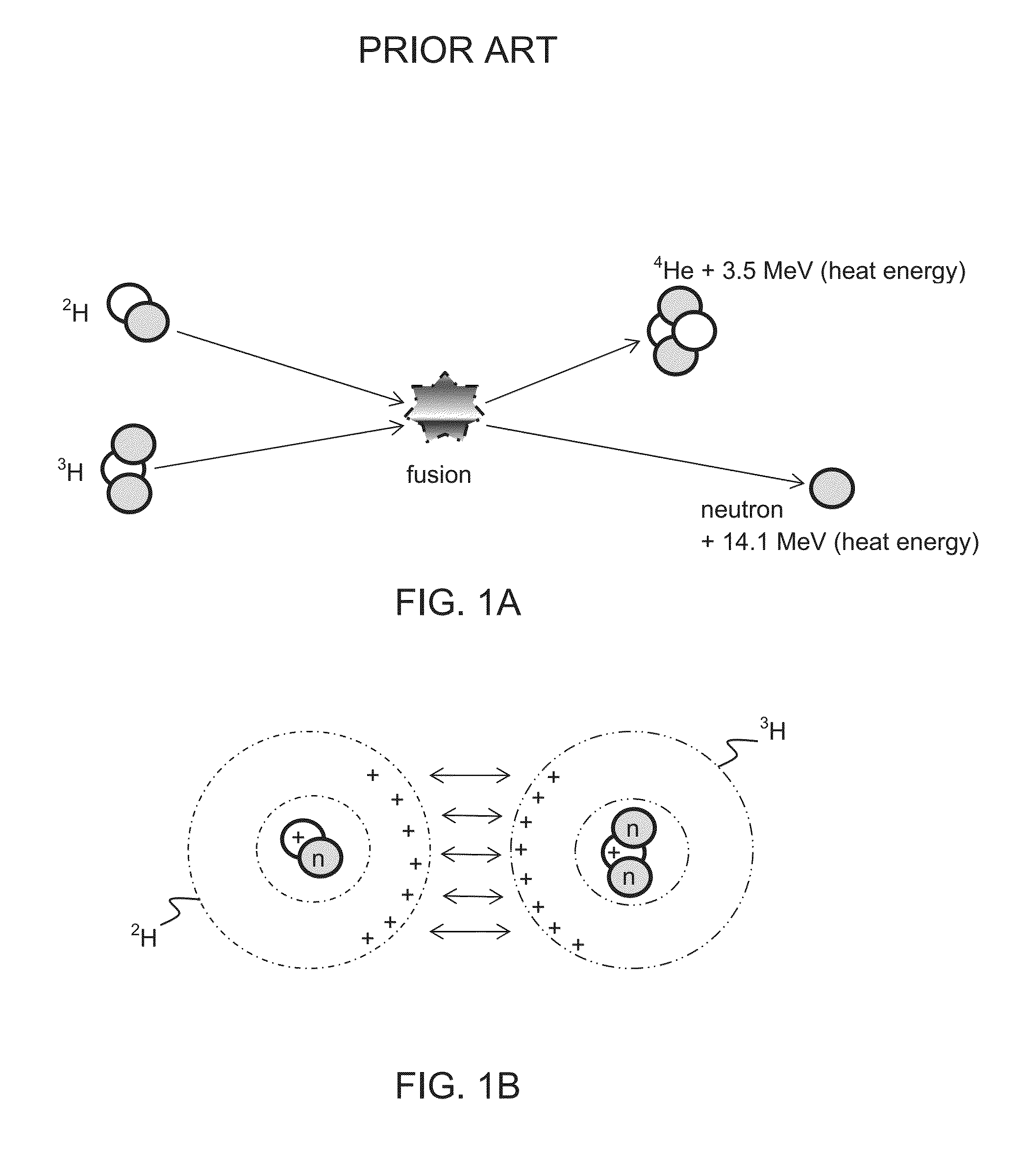
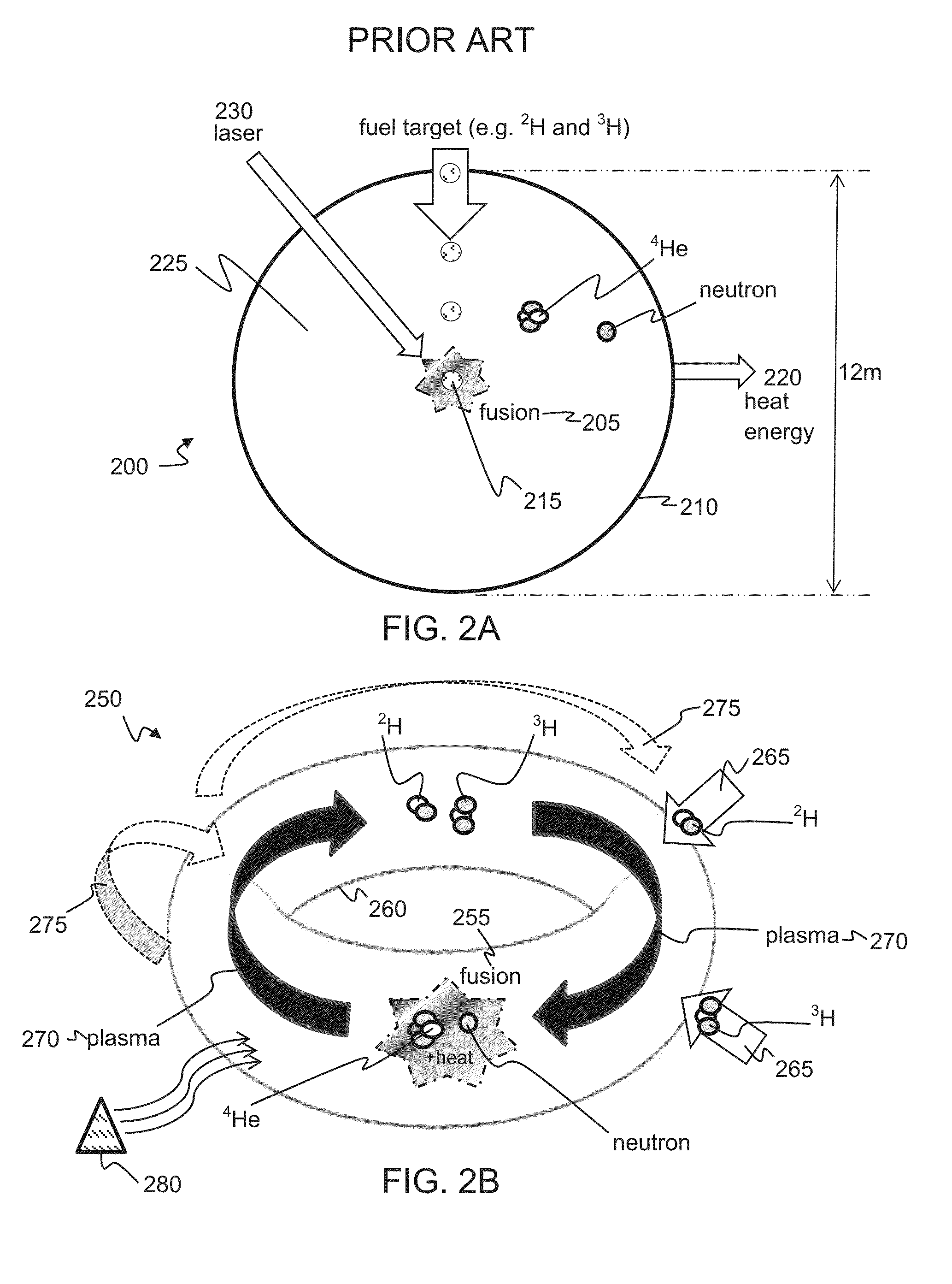
Unfortunately, this technology has not been successfully scaled to produce a power plant, as the system is limited to use of a low reactant density of the deuterium and tritium gases which produces only random collisions and, thus, a low production of energy.
Moreover, an unreasonably high energy is required to initiate the fusion, the system can only be cycled at a slow cycle frequency due to target loading and laser charging limitations, and there is no practical heat exchange method.
It is a costly and inefficient system that leaves costly reactants unreacted due to the low reaction densities inherent to the design.
The magnetic coils 275 also generate a current in the plasma 270, heating it to 10 million ° C. which, unfortunately, is still not hot enough for fusion to occur.
Unfortunately, this technology has not been successfully scaled to produce a power plant, and the system is also limited to the use of deuterium and tritium gases at a low reactant density which produces a low reaction rate and low production of energy.
In addition, an especially problematic condition is that the reaction products are not removed but, rather, mix with the reactants and slow the reaction rate.
Moreover, cycling of the process is impractical due to the large volume of the system which demands a long pump-out time.
As with the LIFE system 200, there is no practical heat exchange method in the ITER system 250, and the ITER system 250 is costly to manufacture, maintain, and operate due to its complexity and inefficiencies.
Although there are theoretical designs for a reactor that is hoped to deliver ten times more fusion energy than the amount needed to heat up the plasma 270 to the required temperatures for fusion to occur, the ITER facility is still not expected to finish its construction phase until at least 2019 and is not expected to begin full deuterium-tritium fusion until at least 2027.

Method used


Image

  • Nuclear fusion using high energy charged particle convergence at a target cathode
  • Nuclear fusion using high energy charged particle convergence at a target cathode
  • Nuclear fusion using high energy charged particle convergence at a target cathode

Examples


example 1

Calculating a Fuel Flow Rate

[0075]The equation describing the energy balance for a representative 2 gigawatt (GW) power plant is as follows and assumes a 100% utilization of reactants:

17.6MeV2H(singlemolecule)+3H(singlemolecule)=2.8198×10⁻¹⁸megajoule(ref:1)2GWatt=(2.8198×10⁻¹⁸megajoule)*(x / sec)[2H(singlemolecule)+3H(singlemolecule)](x / sec)[2H(singlemolecule)+3H(singlemolecule)]=7.0926×10²⁰ / sec(x / sec)[2.0141u2H+3.0160u3H]=7.0926×10²⁰ / sec(x / sec)[3.3234×10⁻²⁴gram2H+5.0082×10⁻²⁴gram3H]=(2.3572milligram2H+3.5522milligram3H) / sec= [2.3572milligram2H(22.4liter / 2.0141gram2H / +3.5522milligram3H(22.4liter / 3.0160gram3H)] / sec=(.02622liter2H+.02638liter3H) / sec

[0076]Accordingly, for a 2 GW power plant, the fuel flow rate should be approximately =1572.9 sccm2H+1582.9 sccm3H!!

[0077]Where:[0078]x / sec=parameter representing the number of 2H+3H reactions required per second to generate 2 GWatt[0079]ex=10 to the x power[0080]MeV=Mega electron volt (energy)[0081]2H=Deuterium[0082]3H=Tritium[0083]GWatt=gig...

example 2

Calculating Relative Locations for the Reactant Injectors and Target Cathode

[0089]One of skill will appreciate that the location of the injectors for the two reactants is determined by their transport time to target. This interval is determined by their mass (resisting acceleration) and their ionization (producing force causing acceleration. The governing equation of rectilinear motion is:

s=½at2

[0090]Where:[0091]s=distance from reactor induction to target[0092]a=acceleration due to the unbalanced force of the ionized reactants in the electromagnetic field[0093]t=the time of transport from the site of induction to the target

[0094]The distance for the 2 reactants to the target can be the same, for example, due to the complimentary inverse relationship of mass to ionization—2 / 3 ratio for mass and 3 / 2 ratio for force due to relative ionization.

example 3

Calculating Target Cathode Size

[0095]One of skill will appreciate that the size of the target cathode should be related to the reactant flow for the reactor, the number of reaction nodes, the output of the reactor, and the size of the reactant nuclei. A configuration that offers a basis for establishing the physical reaction is a monolayer of reactant nuclei covering the faces of the electrode being impacted, recognizing that reactions adjacent to the target are anticipated either from same-side same-direction reactant collision or opposite-side opposite-direction reactant collision. This high density nuclear condition is unique to the teachings provided herein, and it produces a high reaction efficiency, as well as overcomes the inherent limitations in other unsatisfactory development paths at other facilities / programs.

[0096]The true sizes of the atomic and nuclear species under discussion are dependent upon Bose Einstein Condensate behavior of the ionized bosons dependent on local...


PUM


Abstract

A controlled fusion process is provided that can produce a sustained series of fusion reactions: a process that (i) uses a substantially higher reactant density of the deuterium and tritium gases by converging cationic reactants into the higher reaction density at a target cathode rather than relying on random collisions, the converging producing a substantially higher rate of fusion and energy production; (ii) uses a substantially lower input of energy to initiate the fusion; (iii) can be cycled at a substantially higher cycle frequency; (iv) has a practical heat exchange method; (v) is substantially less costly to manufacture, operate, and maintain; and, (vi) has a substantially improved reaction efficiency as a result of not mixing reactants with products.

Description

CROSS-REFERENCE TO RELATED APPLICATIONS[0001]This application claims the benefit of U.S. Provisional Application No. 62 / 002,922, filed May 26, 2014, which is hereby incorporated by reference herein in its entirety.BACKGROUND[0002]1. Field of the Invention[0003]The teachings provided herein are generally directed to systems and methods for obtaining nuclear fusion energy using a high energy charged particle convergence at a target cathode to increase the amount of fusion energy produced in a single fusion cycle.[0004]2. Description of the Related Art[0005]Most will agree that our world needs better sources of energy, source that are more efficient and would reduce the threat to the environment created by our current energy sources. In fact, most will agree that an uncompromising new energy architecture / paradigm is required to allow continued societal development and to avoid habitat and species loss. Current energy usage rewards a small minority of the population to the disadvantage ...

Claims


Application Information

Patent Timeline
IPC IPC(8): G21B1/17
CPCG21B1/17G21B3/006Y02E30/10G21B1/19G21B1/05G21B1/25
Inventor GOLDBERG, ADAM S.
Owner GOLDBERG ADAM S
Learn More