
Device for separating carbon dioxide using silicone separation film and method for manufacturing same

a technology of carbon dioxide and separation film, which is applied in the direction of separation process, dispersed particle separation, membrane separation, etc., can solve the problems of large impact on human social life, high energy consumption, and high cost, and achieves low pressure difference, high energy consumption, and simple method

Active Publication Date: 2016-03-03
ARSTROMA CO LTD
View PDF16 Cites 10 Cited by
  • Summary
  • Abstract
  • Description
  • Claims
  • Application Information

AI Technical Summary

Benefits of technology

The invention uses a ceramic-coated porous silicone membrane to separate carbon dioxide from byproduct gases using a small pressure difference. This eliminates the need for high energy consumption and allows for the production of larger apparatuses. Additionally, the apparatus can be installed in dirty water or under water, making installation easier. The technical effects of this invention include low energy consumption, simpler design, and wider applicability.

Problems solved by technology

Global warming not only disturbs the ecosystem but also has a huge impact on human social life.
However, as oxygen is gradually reduced, the landfill gas is primarily decomposed in an anaerobic digestion process.
Carbon dioxide is particularly a problem when emitted from thermoelectric power plants or steel mills.
This method is advantageous in that it can produce a large amount of liquefied carbon dioxide but disadvantageous in that it requires a lot of energy for cooling.
However, the aromatic polyimide gas separation membrane can be manufactured only at a high temperature of 350 t or above and has problems in heat resistance, durability, and chemical resistance.
However, it is difficult to form a separation membrane having a large size of 10 cm′ or more.
In addition, when partial pressure on both sides is used, a massive amount of energy is consumed, and a separation membrane that can withstand this pressure difference cannot be formed.

Method used


Image

  • Device for separating carbon dioxide using silicone separation film and method for manufacturing same
  • Device for separating carbon dioxide using silicone separation film and method for manufacturing same
  • Device for separating carbon dioxide using silicone separation film and method for manufacturing same

Examples


example 1

Experiment Conducted Using a Porous Silicone Tube as a Separator

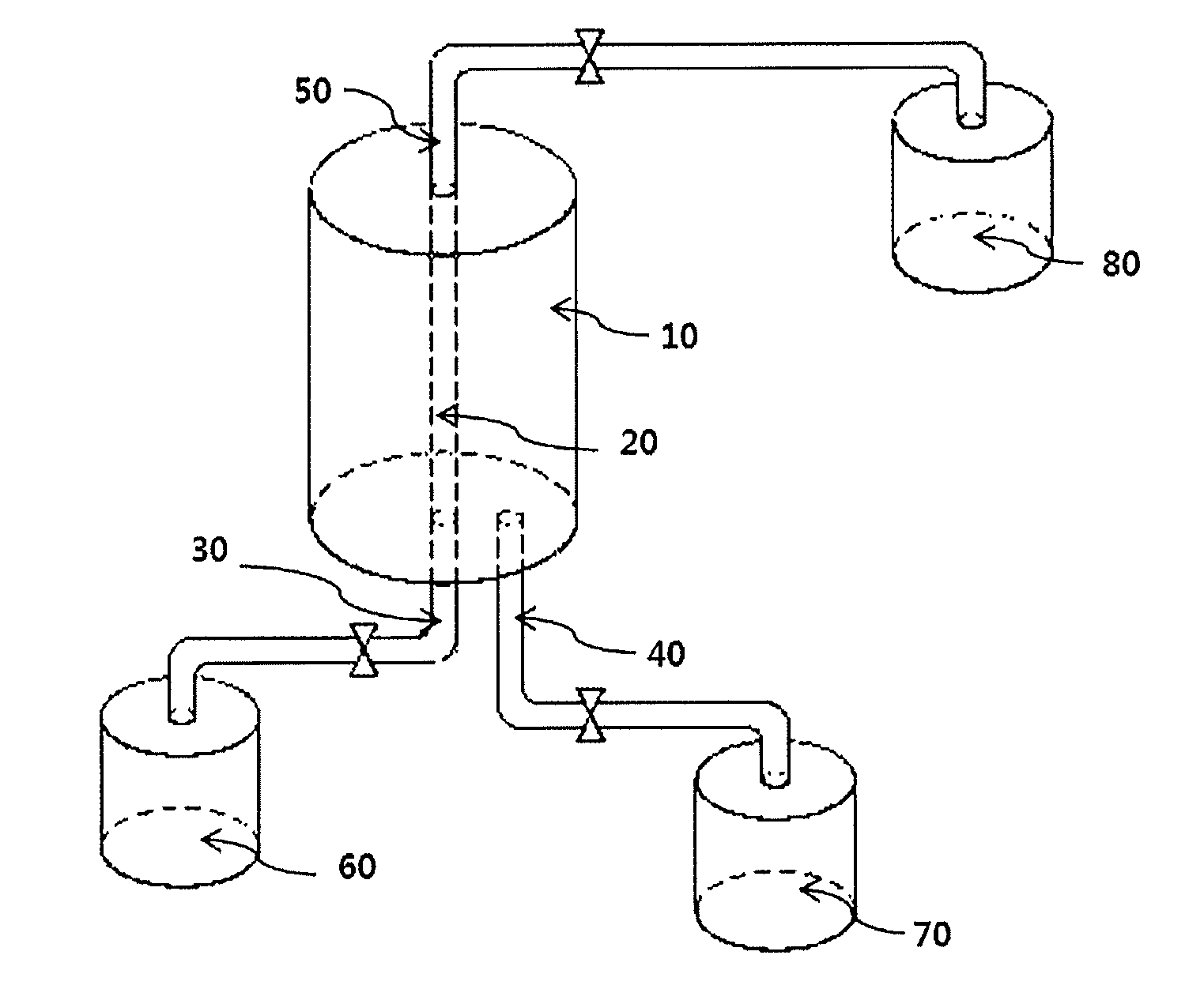
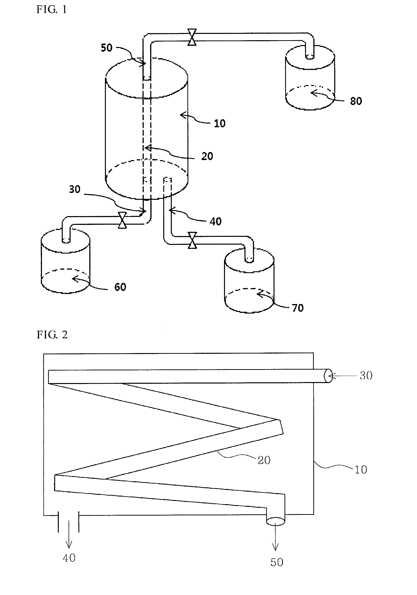
[0079]A porous silicone tube having a thickness of 2 mm was installed as the porous silicone membrane 20 of FIG. 1, and a mixed gas containing 50% carbon dioxide and 50% nitrogen was used as a byproduct gas. The byproduct gas was injected into a reactor at a constant flow rate of 2.5 cc / sec using the MFC.

[0080]As the byproduct gas flowed at the constant flow rate, carbon dioxide permeated through the separator made of the silicon tube. As a result, a collection rate of carbon dioxide separated from the byproduct gas was 94%.

example 2

Experiment Conducted Using a Nanoceramic-Coated Porous silicone Tube as a Separation Membrane

[0081]After 0.5 g of nanoceramic was mixed with 100 g of water, the mixture was dispersed sufficiently using an ultrasonic disperser. Then, a silicone tube having a thickness of 2 mm was immersed in the dispersed mixture for 30 minutes. After 30 minutes, the silicon tube was taken out from the dispersed mixture and dried for 3 to 4 hours at room temperature. This process was repeated three or more times so that the mixture can be evenly coated on the inside and outside of the tube.

[0082]The coated porous silicone tube was installed as the porous silicone membrane 20 of FIG. 1, and a mixed gas containing 50% carbon dioxide and 50% nitrogen was used as a byproduct gas. The byproduct gas was injected into a reactor at a constant flow rate of 2.5 cc / sec using the MFC.

[0083]As the byproduct gas flowed at the constant flow rate, carbon dioxide permeated through the separator made of the silicon tu...

example 3

Example Method of Manufacturing a Carbon Dioxide Separation Membrane by Mixing a Silicone Rubber Raw Material, Ceramic Powder and a Curing Agent and Extruding the Mixture

[0089]First, 980 g of silicon rubber raw material is prepared.

[0090]Then, 10 g of nanoceramic powder having a grain size of 20 nm to 50 μm is mixed with 10 g of benzoyl peroxide which is a curing agent. The mixture is stirred for 10 to 200 minutes at room temperature to evenly mix the nanoceramic powder and the curing agent.

[0091]Then, 980 g of silicon rubber raw material is added to the mixture and kneaded for several hours at room temperature.

[0092]After an extruder is heated to a temperature of approximately 100° C., the kneaded mixture of the ceramic powder, the curing agent and the silicon rubber raw material is put into a hopper of the extruder. Then, a tube is drawn out through an extrusion die having a cross-sectional shape of a tube. The tube is cured for less than one hour in an oven heated to a temperatur...


PUM

PropertyMeasurementUnit
Grain sizeaaaaaaaaaa
Temperatureaaaaaaaaaa
Percent by massaaaaaaaaaa

Abstract

Provided are an apparatus for separating and collecting carbon dioxide and a method of separating carbon dioxide, and more particularly, an apparatus and method of selectively separating carbon dioxide from a byproduct gas using a difference in negative pressure and a difference in carbon dioxide concentration between the inside of a separator, which is made of a ceramic-coated porous silicone membrane and in which the byproduct gas flows, and the outside of the separator in which carbon dioxide is collected.

Description

TECHNICAL FIELD[0001]The present invention relates to an apparatus for separating carbon dioxide from waste gas, and more particularly, to an apparatus for separating carbon dioxide using a separator, which is made of a ceramic-coated porous silicone membrane, and a method of manufacturing the same.BACKGROUND ART[0002]Global warming is now an issue of worldwide concern, and the greenhouse effect caused by carbon dioxide and methane gas plays a significant role in global warming. Global warming not only disturbs the ecosystem but also has a huge impact on human social life. In this regard, efforts are being made in various aspects to reduce atmospheric emissions of carbon dioxide and methane gas.[0003]In sewage treatment plants, waste water treatment plants, landfill sites, etc., organic substances contained in waste generate gas through decomposition. This gas is called landfill gas. At the initial landfill stage, the landfill gas is decomposed in the presence of oxygen. However, as...

Claims


Application Information

Patent Timeline
IPC IPC(8): B01D53/22C01B32/50
CPCB01D53/228B01D53/225B01D2053/221B01D2256/245B01D2257/504B01D2053/223B01D2258/0283B01D69/12Y02C10/10B01D71/70B01D71/024B01D2259/80B01D2259/816Y02C20/40B01D53/22
Inventor KIM, GWAN, SHIGSHIN, KY, YEONG
Owner ARSTROMA CO LTD
Learn More