Conductive polymer material and substrate

Active Publication Date: 2016-03-17
SHIN ETSU CHEM IND CO LTD
View PDF6 Cites 16 Cited by
  • Summary
  • Abstract
  • Description
  • Claims
  • Application Information

AI Technical Summary

Benefits of technology

[0037]Besides, the conductive polymer material of the present invention can be improved in its conductivity by being exposed to a light having a wavelength of 140 to 400 nm or an electron beam after it is applied onto the substrate or the like to form a film thereon.
[0038]The conductive film thus formed has excellent conductivity and transparency, so that it may function as a transparent electrode layer.
[0039]As mentioned above, in the conductive polymer material of the present invention, the dopant polymer of the component (B) which contains a strongly acidic sulfo group forms the composite together with the π-conjugated polymer of the component (A), and moreover, the amphoteric ion compound of component (C) is added, whereby acidity of solution is lowered, the agglomeration of the particles with the passage of ti

Problems solved by technology

As mentioned above, there is a problem that the conductive polymer solution in which a composite formed from a dopant polymer having a sul

Method used


Image

  • Conductive polymer material and substrate
  • Conductive polymer material and substrate
  • Conductive polymer material and substrate

Examples


Example

Preparation Example 1

[0151]A solution in which 12.5 g of Dopant polymer 1 had been dissolved in 1,000 mL of ultrapure water was mixed with 3.82 g of 3,4-ethylenedioxythiophene at 30° C.

[0152]Into the resulting mixed solution was slowly added an oxidation catalyst solution in which 8.40 g of sodium persulfate and 2.3 g of ferric sulfate had been dissolved in 100 mL of ultrapure water while stirring the mixed solution and keeping the temperature thereof at 30° C., and the reaction was carried out for 4 hours under stirring.

[0153]Into the reaction solution thus obtained was added 1,000 mL of ultrapure water, and about 1,000 mL of the solution was removed by ultrafiltration. This procedure was repeated 3 times.

[0154]Subsequently, 200 mL of sulfuric acid diluted to 10% by mass and 2,000 mL of ion-exchanged water were added to the solution treated with the ultrafiltration, and about 2,000 mL of the treated solution was removed by ultrafiltration. After 2,000 mL of ion-exchanged water was ...

Example

Preparation Example 2

[0160]Procedure of Preparation Example 1 was repeated, except that 10.0 g of Dopant polymer 2 was used in place of 12.5 g of Dopant polymer 1, the blending amount of 3,4-ethylenedioxythiophene was changed to 2.41 g, the blending amount of sodium persulfate was changed to 5.31 g, and the blending amount of ferric sulfate was changed to 1.50 g, to obtain Conductive polymer composite dispersion 2.

Example

Preparation Example 3

[0161]Procedure of Preparation Example 1 was repeated, except that 12.0 g of Dopant polymer 3 was used in place of 12.5 g of Dopant polymer 1, the blending amount of 3,4-ethylenedioxythiophene was changed to 2.72 g, the blending amount of sodium persulfate was changed to 6.00 g, and the blending amount of ferric sulfate was changed to 1.60 g, to obtain Conductive polymer composite dispersion 3.


PUM

PropertyMeasurementUnit
Nanoscale particle sizeaaaaaaaaaa
Molecular weightaaaaaaaaaa
Electrical conductoraaaaaaaaaa

Abstract

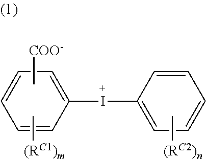
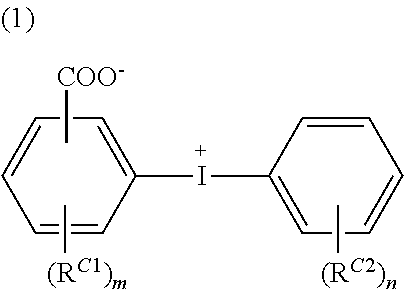
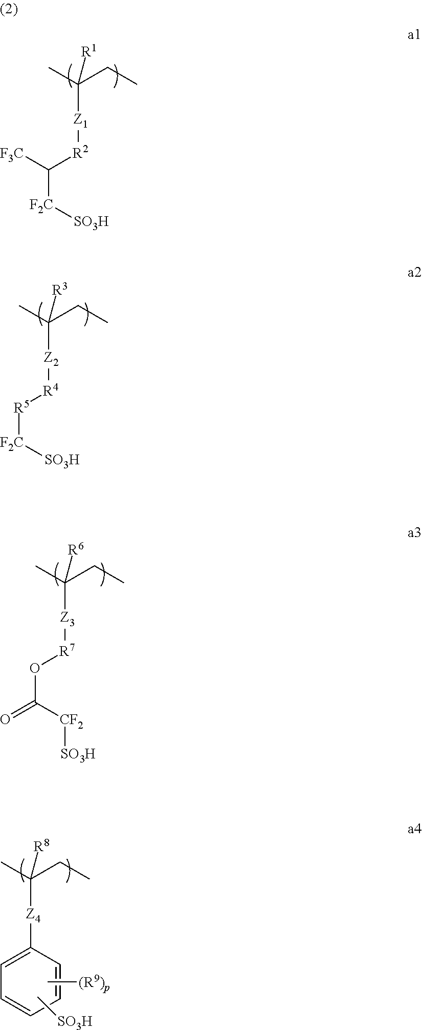
A conductive polymer material includes a π-conjugated polymer, dopant polymer which contains a repeating unit having a sulfo group and has a weight-average molecular weight in the range of 1,000 to 500,000, and amphoteric ion compound represented by the following general formula (1),
wherein RC1 and RC2 independently represent a linear, branched, or cyclic alkyl group having 1 to 10 carbon atoms, a linear, branched, or cyclic alkoxy group having 1 to 10 carbon atoms, an acyl group having 2 to 10 carbon atoms, an acyloxy group having 2 to 10 carbon atoms, an alkoxycarbonyl group having 2 to 10 carbon atoms, a hydroxyl group, a nitro group, a halogen atom; and “m” and “n” are each an integer of 0 to 4. A conductive polymer material with low acidity that suppresses the agglomeration of particles with overtime, with an excellent stability in a solution state can be provided.

Description

BACKGROUND OF THE INVENTION[0001]1. Field of the Invention[0002]The present invention relates to a conductive polymer material and a substrate having a conductive film formed thereon by using the conductive polymer material.[0003]2. Description of the Related Art[0004]A polymer having a conjugated double bond (i.e. π-conjugated polymer) does not show a conductivity by itself; however, if an appropriate anionic molecule is doped therein, it can express a conductivity, thereby giving a conductive polymer material (i.e. conductive polymer composition). As to the π-conjugated polymer, polyacetylene; (hetero) aromatic polymers such as polythiophene, polyselenophene, polytellurophene, polypyrrole, and polyaniline; a mixture thereof, etc., are used; and as to the anionic molecule (dopant), an anion of sulfonic acid type is most commonly used. This is because a sulfonic acid, which is a strong acid, can efficiently interact with the aforementioned π-conjugated polymers.[0005]As to the anion...

Claims


Application Information

Patent Timeline
IPC IPC(8): C08L81/02B05D1/00B05D3/06C08L53/00H01B1/12
CPCC08L81/02H01B1/125B05D3/065B05D1/005C08L53/00C08G2261/1424C08G2261/314C08G2261/3221C08G2261/3223C08G2261/3225C08G2261/512C08G2261/794C08G2261/3226C08L65/00C09D11/52C08L25/18C08L33/16H10K85/1135C08K5/03C08K5/09
Inventor HATAKEYAMA, JUNNAGASAWA, TAKAYUKI
Owner SHIN ETSU CHEM IND CO LTD
Why Eureka
Try Eureka