Method and apparatus for laser quenching

a laser quenching and treatment technology, applied in heat treatment apparatus, manufacturing tools, furnaces, etc., can solve the problems of limited use of laser quenching, limited depth of hardened layer by laser quenching process in the prior art, and low productivity, so as to improve the productivity and the depth of hardening, the effect of small hardening depth

Active Publication Date: 2016-03-17
WUHAN HIVALUE INTELASER LTD
View PDF1 Cites 15 Cited by
  • Summary
  • Abstract
  • Description
  • Claims
  • Application Information

AI Technical Summary

Benefits of technology

[0018]It is an objective of the invention to provide a method for laser quenching on repeated scans based on a scanning galvanometer that can substantially improve the productivity and the depth of hardening by ...

Problems solved by technology

However, the melting laser quenching process significantly alters surface roughness of the metal material, so use thereof is limited in circumstances where a high precision is required and a subsequent machining is forbidden.
As surface melting is not allowed in laser quenching, neither excessive laser power or laser power density nor excessive treating duration is to be adopted, therefore, the depth of a hardened layer by laser quenching processes in the prior art is extremely limited according to the three equations described above.
Although the process is simple and does not require a complex control system and programming procedure, it has a relatively low processing efficiency.
Besides, considering restrictions of thermal conduction properties and the hardenability of the ...

Method used


Image

  • Method and apparatus for laser quenching
  • Method and apparatus for laser quenching
  • Method and apparatus for laser quenching

Examples


embodiment 1

A Laser Quenching Process on Repeated Scans Applied to Laser Quenching a Large-Scaled Gear

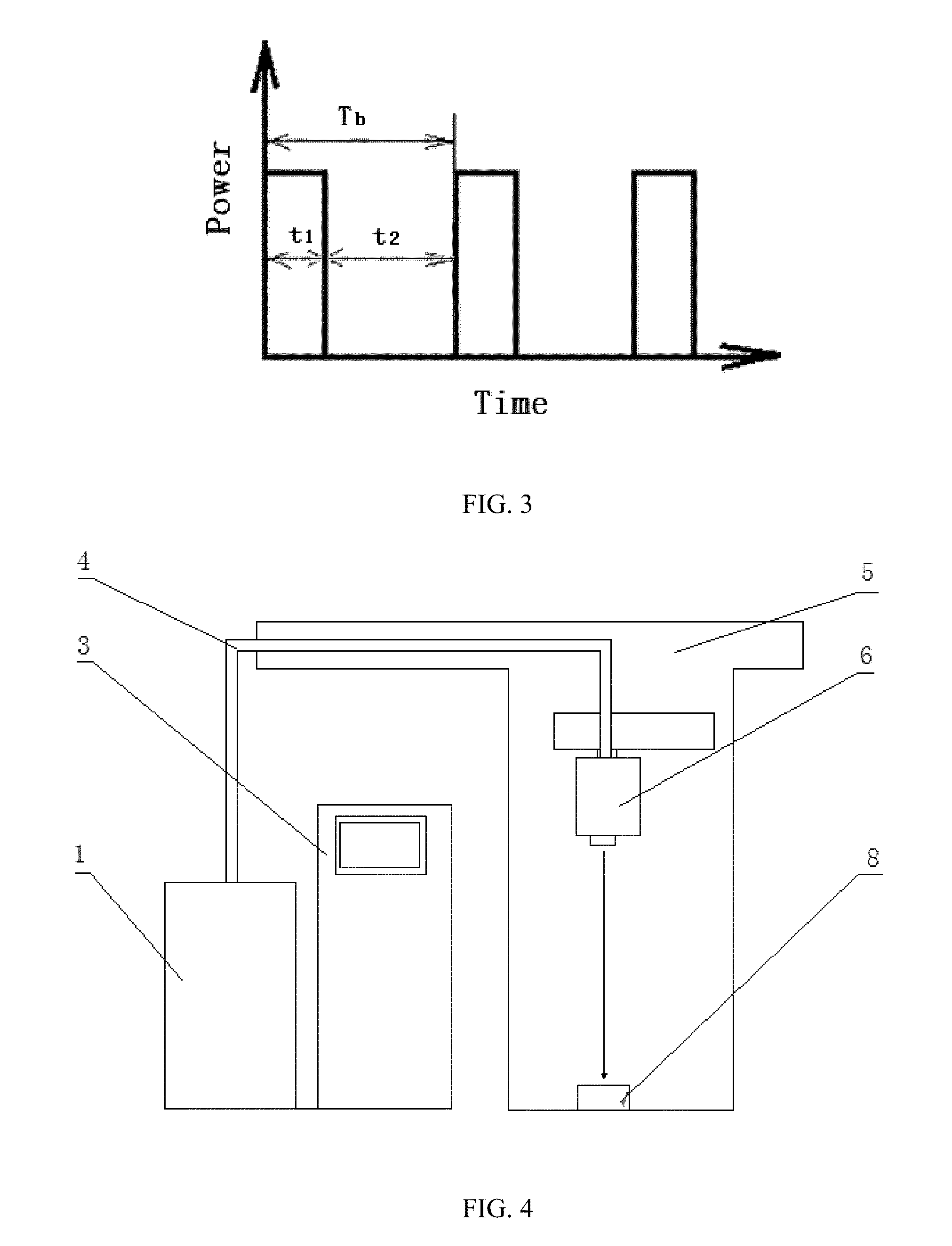
[0122]A diode laser is employed to perform laser quenching on a large-scaled 42 CrMo gear according to the embodiment. The spot size is φ6 mm, the laser power is 6000 W, the processing unit is a 6 mm×15 mm rectangle, the scanning speed is 1000 mm / s, the scanning times is 50, the duration of a continuous treatment t1 is 0.015 s, the interval of two treatments t2 is 0.0167 s, the quenching period T is 1.6 s, the relative moving speed is 400 mm / min, and the direction of the vector of the relative moving speed is perpendicular to the longitudinal direction of the processing unit. A quenched region with a width of 15 mm is obtained by single-track quenching without an overlap and the depth of hardening is 0.8 mm.

[0123]The temperature curve of the workpiece surface during laser quenching on repeated high power scans is shown in FIG. 5.

[0124]Generally, no conventional motion mechanism can reach su...

embodiment 2

A Laser Quenching Process on Repeated Scans Applied to Laser Quenching a Large-Scaled Roll

[0127]A CO2 laser with a wavelength of 10.6 μm is employed to perform laser quenching on a large-scaled 75 CrMnMo roll according to the embodiment. The spot size is φ5 mm, the laser power is 8000 W, the processing unit is a 5 mm×35 mm rectangle, the scanning speed is 350 mm / s, the scanning times is 12, the duration of a continuous treatment t1 is 0.1 s, the interval of two treatments t2 is 0.125 s, the quenching period T is 2.7 s, the relative moving speed is 300 mm / min, and the direction of the vector of the relative moving speed is perpendicular to the longitudinal direction of the processing unit. A quenched region with a width of 35 mm is obtained by single-track quenching with an overlap of 2 mm. Spray a special SiO2 light-absorbing material on the workpiece surface before laser quenching, and start laser quenching until the light-absorbing material is dried. The depth of hardening can...

embodiment 3

A Laser Quenching Process on Repeated Scans Applied to Laser Quenching A Large-Scaled Mold

[0129]A fiber laser is employed to perform laser quenching on a large-scaled 50 CrNiMo mold according to the embodiment. The spot size is 6 mm×6 mm, the laser power is 12000 W, the processing unit is a 6 mm×140 mm rectangle, the scanning speed is 420 mm / s, the scanning times is 7, the duration of a continuous treatment t1 is 0.333 s, the interval of two treatments t2 is 0.349 s, the quenching period T is 4.8 s, the relative moving speed is 300 mm / min, and the direction of the vector of the relative moving speed is perpendicular to the longitudinal direction of the processing unit. A quenched region with a width of 140 mm is obtained by single-track quenching and the depth of hardening is 0.6 mm. The temperature curve of the workpiece surface during laser quenching on repeated high power scans is shown in FIG. 7.

[0130]Similarly to embodiment 1, melting in a workpiece surface occurs if a lase...


PUM

PropertyMeasurementUnit
Lengthaaaaaaaaaa
Temperatureaaaaaaaaaa
Speedaaaaaaaaaa

Abstract

Provided are a method and an apparatus for laser quenching. The method takes the advantage of a high jumping speed of a scanning galvanometer, and adopts the method of heating on multiple or even high frequency repeated scans instead of on a single scan in prior art for laser quenching, wherein the laser energy is fed into the surface of a workpiece by way of short time and multiple superimposed heating, cumulatively, the laser energy absorbed by the metal base is increased and the depth of thermal conduction is improved also. The apparatus includes a laser, a control system, a light guiding system, a mechanical motion device and a scanning galvanometer. Therefore, even though the used laser power is relative high, the surface temperature of a metal object can be always restricted below its melting point and the heat can be conducted from the surface to the internal of a workpiece by thermal conduction constantly and effectively as a result of high scanning speed and the introduce of time interval at scanning, so that melting in the metal surface can be avoided, and the depth of the austenitizing region in the surface of the workpiece and the productivity of laser quenching can be significantly improved.

Description

FIELD OF THE INVENTION[0001]The present invention relates to the laser surface hardening treatment technology, and more particularly to a method and an apparatus for laser quenching on repeated scans based on a scanning galvanometer, and the invention is particularly suitable for quenching a surface of a large-sized metal workpiece.BACKGROUND OF THE INVENTION[0002]Laser quenching technology, also known as laser heat treatment or laser transformation hardening process, employs a laser beam to irradiate a metal workpiece, enabling surface temperature thereof to rise above austenitizing temperature Ta. After removal of the laser beam, temperature of the laser treated region drops below the temperature of martensitic transformation quickly, and a martensitic hardened layer is formed in the surface area because the cooling rate of the heated region is greater than the critical cooling rate of quenching due to rapid heat conduction of the base material which is still in the room temperatu...

Claims


Application Information

Patent Timeline
IPC IPC(8): C21D1/09C21D1/70
CPCC21D1/70C21D1/09
Inventor ZENG, XIAOYANHU, QIANWUZHENG, YINLANJIANG, MINGLI, CHONGYANGREN, ZHAOLI, KUN
Owner WUHAN HIVALUE INTELASER LTD
Why Eureka
Try Eureka